Hello all-
I was looking into a low voltage tube amp, but the more I learn about tubes, the more the low voltage option seemed to diminish. Odds are, I could not get good enough output with my headphones to warrant building. I did a little searching of the archives and came upon ashok's design (I had searched before, but had somehow missed this one), which I think looks fairly nice. Attached is the amp and regulated power supply:

I would use this with a 6DJ8 variant, instead of the ECC83. Does anyone have any opinions as to how this would sound? What about the regulated PS? What voltage rating should my transformer be? Current rating?
Thanks
I was looking into a low voltage tube amp, but the more I learn about tubes, the more the low voltage option seemed to diminish. Odds are, I could not get good enough output with my headphones to warrant building. I did a little searching of the archives and came upon ashok's design (I had searched before, but had somehow missed this one), which I think looks fairly nice. Attached is the amp and regulated power supply:
I would use this with a 6DJ8 variant, instead of the ECC83. Does anyone have any opinions as to how this would sound? What about the regulated PS? What voltage rating should my transformer be? Current rating?
Thanks
I am by no means a wiz at biasing or working with tubes apparently, and would prefer to do a tried design instead of work on my own as of now. I worked with the low voltage tubes, and now my power supply tranny is messed up. (don't ask) I also nearly fried a few things...
The need for tubes is killing me... I just want something up and running. If I had the money, I'd buy a kit. But, I cannot afford it. I doubt I could get anything running with another tube and experimental values (I probably wouldn't even get this running).
The need for tubes is killing me... I just want something up and running. If I had the money, I'd buy a kit. But, I cannot afford it. I doubt I could get anything running with another tube and experimental values (I probably wouldn't even get this running).
6DJ8
Hi Needtubes,
I am working on a 6DJ8 circuit with less components. It still uses an ss output with a 40 volt dc supply. It has a class A output . Will post the circuit and performance in a day or two.
Am trying to make it so that there is no pcb required.
Cheers.
Ashok.
Hi Needtubes,
I am working on a 6DJ8 circuit with less components. It still uses an ss output with a 40 volt dc supply. It has a class A output . Will post the circuit and performance in a day or two.
Am trying to make it so that there is no pcb required.
Cheers.
Ashok.
Basic scheme
Hi Needtubes,
Tubes and low voltage I think is generally frowned upon. But if we can squeeze out decent performance it might be worth the trouble designing one.
My intention was to use a power supply that used capacitors rated at 50 Volts or lower. This keeps costs down. The only low priced low voltage tube that I can get is the 6DJ8 and the 6922.
So when I saw your post I decided to complete my design quickly.
The components have exceeded my target number but are essential for good performance.
Frequency response into a 300 ohm load is -0.5 db at 20Hz and about -0.1db at 20kHz. Distortion is less than 0.1% at nearly 4 volts peak ( 2.8 V rms). That will be about 26.7 milli watts into 300 ohms. With a 96db per mW headphone you will get 110 db!!
The output impedance is also very low - about 1 ohm over most of the bandwidth and rising to about 8 ohms at 20Hz. That I think is quite good.
The power supply is a simple capacitance multiplier. The 5.6 k ohm resistor may have to be chosen to get about 3 volts drop across the collector emitter. This circuit has not been tested yet.
I have collected the parts and should be able to do this in a couple of days. The bootstrap capacitor is essential to improve open loop gain and reduce distortion.
The output is a class A stage with an idle current of about 0.06 Amp. Q2 is a current source with a 9.1 volt zener at the gate.
All resistors are 1/4 watt and only the 3.9K resistor is a 1/2 watt type. Q1 and Q2 will have to be mounted on a simple heat sink. They don't dissipate equal amounts of heat.
Cheers.
Ashok.
Attachments
I like this circuit. Shouldn't be all that expensive to build, and if it sounds good, should be well worth it. ")
R8... the 300-ohm resistor- I am assuming this is the load, correct?
If I want a volume control, can I just add a 50k pot in front without changing anything?
Thanks
R8... the 300-ohm resistor- I am assuming this is the load, correct?
If I want a volume control, can I just add a 50k pot in front without changing anything?
Thanks
R8
Yes R8 is the load. Actually it should have been a large value resistor say 100K . This would permit the output capacitor to charge even if the phones are not connected. Otherwise you would get a bang when you plugged the phones in .
So if R8 is 100k the phones load is not shown ! It will be in parallel with R8.
You can use a 50 K pot for volume. That's what I intend using.
Cheers.
Ashok.
Capacitance multiplier doubt.
Hi Tim,
Check out http://sound.westhost.com/project15.htm
This describes the capacitance multiplier.
Q3 is the capacitance multiplier device. The collector base
resistor should ensure that you have enough voltage across the transistor collector emitter to keep it in the active zone - above 1.5 volts under all supply voltage conditions.
Cheers,
Ashok.
Hi,
Don't you mean that the function of R8 is to PREVENT the coupling cap from charging when no load is attached?
Yup. And you can just as well do that with a tube too.
Why it isn't used more often is beyond me, it offers a lot of advantages for very little outlay.
Cheers,
This would permit the output capacitor to charge even if the phones are not connected. Otherwise you would get a bang when you plugged the phones in .
Don't you mean that the function of R8 is to PREVENT the coupling cap from charging when no load is attached?
Is Q3 what's known as a capacitor multiplier? Uh I think...
Yup. And you can just as well do that with a tube too.
Why it isn't used more often is beyond me, it offers a lot of advantages for very little outlay.
Cheers,
R8
Hi Frank,
R8 is a large value resistor which permits a dc path to ground. The capacitor will have to charge up to the dc value between output and ground. This ensures that there in no dc on the output when the phones is plugged in. If R8 is missing , the capacitor will charge through the phones and cause a loud transient crack in the headphones - if it is large enough it can blow the headphone coil and diaphragm.
BUT, I am not sure at the moment how fast the dc voltage builds up at the output. If it is slow enough this problem will be reduced.
The capacitance multiplier itself has and RC value of about 1 sec or so. Let me check this . I had overlooked it.
About the capacitance multiplier.
The effective capacitance = hfe x capacitance value.
With a single transistor we can easily have a x 125 factor. With a Darlington we can get a factor in excess of x 1500. Maybe a tube will not be able to match this easily. I have not looked at it -- but maybe!
Cheers,
Ashok.
Hi,
O.K., we're talking about the same thing...just expressing it differently.
As far as the value of R8 is concerned I think 100K should be fine.
What I usually do is add a mute switch that shorts the output to ground while the circuit warms up besides having the bleeder resistor.
The situation is different when a cap multiplier is used in regular high voltage tube circuits.
No need to tell you that a multiplication factor of *100 at 200 to 300V is massive as far as Joules are concerned.
While you could use a penthode with a mu of 1000+, it won't have much practical use and will quite possibly add too much noise to the psu.
Cheers,
R8 is a large value resistor which permits a dc path to ground. The capacitor will have to charge up to the dc value between output and ground.
O.K., we're talking about the same thing...just expressing it differently.
As far as the value of R8 is concerned I think 100K should be fine.
What I usually do is add a mute switch that shorts the output to ground while the circuit warms up besides having the bleeder resistor.
With a single transistor we can easily have a x 125 factor. With a Darlington we can get a factor in excess of x 1500. Maybe a tube will not be able to match this easily. I have not looked at it -- but maybe!
The situation is different when a cap multiplier is used in regular high voltage tube circuits.
No need to tell you that a multiplication factor of *100 at 200 to 300V is massive as far as Joules are concerned.
While you could use a penthode with a mu of 1000+, it won't have much practical use and will quite possibly add too much noise to the psu.
Cheers,
Switch on dc thump
I checked the dc voltages. The dc rail comes up rather slowly , about two seconds or more. In addition the dc at the output seems to have one spike less than a volt in amplitude and a bump less than 0.2 volts that settles down in a few seconds. Looks like the phones may not be stressed after all during switch on.
BUT the resistor R8 (100K ohms) must be there. If the output is left open and the system switched on the output dc will go up to about 20 odd volts and the output capacitor will not be charged. When the headphone is plugged in the capacitor will charge up to the 20 odd volts through the phones and cause a nasty 20 volt spike in the headphones - something that we want to avoid.
Cheers.
Hello-
I have some questions about parts selection.
I plan on using fairly high quality components- Elna Cerafine caps, Orange Drop caps, Vishay/Dale resistors, etc. However, I am quite limited on the Elnas. What voltage rating should C3 and C4 be? The only Elnas I have access to are 100uF, 100V and 100uF 35V for those. Will the 35 V be ok?
Can I use a 16V cap for C2?
Will .47uF be large enough for the input coupling cap? That is as large of an Orange Drop as I can get. Is a polypropylene Orange Drop better than a Solen metallized polypropylene cap?
Should the 22k resistors be 22.1k or 22k? I can get either.
Thanks
Part ratings.
Hi Needtubes,
All resistors are 1/4 watt except R6-3.9K which should be at least 1/2 watt. It dissipates about 0.3 watts. A 1 watt will be cooler but I don't think it should matter if you use a 1/2 watt device.
Capacitors: C2 can be a 16 volt device.
C3 and 4 can be 35 volt devices as they have much less voltage across them in operation. C5,6 and 7 are supply caps operating at 40 volts or so and should be rated at least 50 volt.
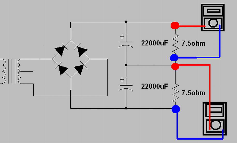
I am going to use 1N4007 x 4 as the bridge rectifier. The heater also will be run on 6 volt ac . I will solder a 470 ohm resistor to each heater terminal. The free end of the resistors will be taken to circuit ground.
You can add a snubber cap - say 0.01uF 100V across each diode.
The supply current per channel is about 70 mA .
C1 can be 0.47 uF 63 volts. THe -3db frequency atthe input is about 7Hz with a 1uF cap and about 15 Hz with a 0.47 uF cap.
This might be quite OK in practice. Check it out in practice.
With C1=0.47uF and R01 changed to 39K and R9 to 150 K you should have about the same LF response. The 39K will degrade the S/N ratio as it is in series with the input. But I have not checked by how much. Probably not enough to cause any trouble as this is not really a pre amp stage. Best method is to try it out.
About the Orange drop and Solen parts. As far as I know all pp and polyester caps are made of metallised plastic film. I find the Orange drop capacitors very good and I remember seeing a report somewhere on the web that the lowly ( cost wise) Orange Drop caps were tested to be as good audibly as some other exotic caps. I would go for the Orange Drop without a second thought.
I should be able to work on my circuit today. We should compare results. My caps are all from Philips.
About 22k or 22k1 parts. Use anything you want. Make sure that both channels are identical. If any parts are reasonably critical , they should be R5 - 1Kohm, R7-82 ohms, and R3 - 18 Kohm. Remember that R8 is 100 Kohm ( anything from 10K to 100 K ohms is OK ) and the headphone output is parallel with this resistor.
Cheers.
Hi Needtubes,
All resistors are 1/4 watt except R6-3.9K which should be at least 1/2 watt. It dissipates about 0.3 watts. A 1 watt will be cooler but I don't think it should matter if you use a 1/2 watt device.
Capacitors: C2 can be a 16 volt device.
C3 and 4 can be 35 volt devices as they have much less voltage across them in operation. C5,6 and 7 are supply caps operating at 40 volts or so and should be rated at least 50 volt.
I am going to use 1N4007 x 4 as the bridge rectifier. The heater also will be run on 6 volt ac . I will solder a 470 ohm resistor to each heater terminal. The free end of the resistors will be taken to circuit ground.
You can add a snubber cap - say 0.01uF 100V across each diode.
The supply current per channel is about 70 mA .
C1 can be 0.47 uF 63 volts. THe -3db frequency atthe input is about 7Hz with a 1uF cap and about 15 Hz with a 0.47 uF cap.
This might be quite OK in practice. Check it out in practice.
With C1=0.47uF and R01 changed to 39K and R9 to 150 K you should have about the same LF response. The 39K will degrade the S/N ratio as it is in series with the input. But I have not checked by how much. Probably not enough to cause any trouble as this is not really a pre amp stage. Best method is to try it out.
About the Orange drop and Solen parts. As far as I know all pp and polyester caps are made of metallised plastic film. I find the Orange drop capacitors very good and I remember seeing a report somewhere on the web that the lowly ( cost wise) Orange Drop caps were tested to be as good audibly as some other exotic caps. I would go for the Orange Drop without a second thought.
I should be able to work on my circuit today. We should compare results. My caps are all from Philips.
About 22k or 22k1 parts. Use anything you want. Make sure that both channels are identical. If any parts are reasonably critical , they should be R5 - 1Kohm, R7-82 ohms, and R3 - 18 Kohm. Remember that R8 is 100 Kohm ( anything from 10K to 100 K ohms is OK ) and the headphone output is parallel with this resistor.
Cheers.
Status.
Hi Needtubes,
The amp has not yet been soldered. I am off to collect the transformer today. Here the component shops are just 6 Km away from home. In fact everything is within a radius of about 15 Km from home !
Hopefully it will be ready tomorrow. Will keep you posted.
I am making a pcb because it is really hard to make a point to point connection neatly. I will have a spare board. If it works well I can mail one board to you.
Cheers.

- Status
- This old topic is closed. If you want to reopen this topic, contact a moderator using the "Report Post" button.
- Home
- Amplifiers
- Headphone Systems
- ashok's tube/ss hybrid headphone amp