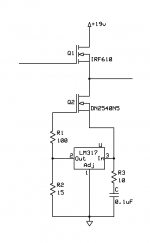
Suggestion: for some good noise reduction cascode the LM317 current source with a DN2540N5 depletion mode mosfet. I'm always looking for ways to wedge in a d-mosfet! 
See figure 13C, page 4, in Walt Jung's audio current source article here
http://waltjung.org/PDFs/Sources_101_P2.pdf
then compare the graph 13D for the cascode with just the LM317 current source alone in figure 10B. With the cascode your rejection stays below 110dB, on out to 200kHz, vs. just 60dB. That 110dB rejection is also lower than just the depletion mosfet current source alone, as he shows in figure 12B.
Attachments
Last edited:
Funny you should mention that, I've got 30 PCBs for that CCS waiting to be populated on my workbench. The problem using that though is threefold.
First, the voltage drop across it is greater, limiting the voltage swing. With a 19v power supply, assume a 3v drop across the 317, 5 volts across the MOSFET, and leave a volt or so at each end for headroom. Now you've only got 9v of swing. It should be enough, but by DC coupling you're setting an operating point that may or may not be ideal. I set a pretty decent one, but didn't plan on the extra voltage drop from a depletion mode MOSFET. That would cut my voltage swing down from 9 to 5.5 volts making the set point unusable (11.2v - 4.5v - 6.5v = 0.2v swing). This means I would have to alter the setpoint by lowering the gain to about 1, which would eliminate the whole point of a gain stage. Alternately, I could AC couple the output stage but this would add complexity, cost, and another capacitor in the chain.
The second problem is increased cost, complexity, and space taken up. I was aiming for simple and low cost for the beginner, vice an ultimate cost no-object amp. Right now there's only 10 resistors, two pots, six three pin devices, and a half dozen caps. I literally built it from my (frighteningly expansive) junk box.
Third, 110 db is a really good number already. That's as good as the resolution of most good DACs. I don't think I could tell the difference between 110 and 130db.
There will be more noise coming from the front end than the source follower anyway. Let's do a quick analysis. I did design in some noise rejection, but it's not perfect. Let's use 1v of noise just for an easy to work with number. Starting from the left, the voltage divider for the virtual ground will give us 3.25/19 = 0.171v. Voltage gain is -1300/560 = -2.32, so there's approximately -.4v on the JFET drain. But there will also be current flowing through the JFET from the power supply, and at the drain it will be 11.2/19 = 0.59v. So the net will be +0.19/1 or 19% of the PSU noise will be injected. Not a great PSRR, but better than many circuits.
I'm less concerned about the PSRR - it's easy enough to regulate the power supply (although I thought I was already using a regulated power supply) or add filtering. My big problem is with static and noise. There's a constant hiss. Whenever I touch the gate of the JFET, or the RCA input jacks, or the source (I'm using a Zune) the hiss gets much louder.
Here's an even simpler 9v version. I really like the simplicity/synchronicity of this one. The LED provides power indication and JFET bias, and the output current can be selected via the resistor on the LM317. Quite elegant and almost usable as a portable amp (maybe with some Li-Po batteries in series?). Too many designs to try out!
Attachments
Whoops - I forgot to circle back to the thread after I posted above.
All good points. I was thinking that the extra parts would probably go against the low parts count design goal. As for the voltage drops, they probably can be a lot less. At the low currents involved the LM317 data sheet shows a dropout around 1.3V, if I'm reading that right. From the DN2540 data sheet it looks like the part would also work at lower voltages, even though it is good for 400V. But good point about the (lack of) need for more rejection here. May be a moot issue.
I don't have any ideas on the hiss and static issues, but I do like your reduced-calorie 9V design!
I'm still searching for a device with a low Vgs and high Idss for the source follower role. Most MOSFETS have at least +2v and it goes up to about +4v at 100ma. JFETS have about a -0.1v Vgs that goes more negative with increasing Idss current, up to several volts. With only 9v to work with, a Vgs of -0.1 to -0.5v is ideal. Any JFET will work as a source follower, but five to ten 2sk170s in parallel are pretty ideal.
> Assuming I have 5 pairs of Jfets. Each pair is made of 2 matched Jfets. Do the 5 pairs need to match each other? So A and B make a pair and C and D make a pair.. do A/B need to match C/D?
No. But A & C should be in parallel (say the top device), and B // D (the bottom device).
Also A & B should be thermally coupled (by thermal glueing face to face, or use a DUal JFET heatsink) for best thermal tracking (DC stability).
Same applies to C & D.
Hope you don't mind me chipping in.
I have a similar set up in the output stage of my preamp which was published at the blowtorch thread about 5 years ago.
http://www.diyaudio.com/forums/soli...rls-blowtorch-preamplifier-21.html#post902247
Patrick
.
Attachments
Last edited:
hi all,
i ve took the chance and tried to build a source follower headphone amp using 10 2sk170 in parallel in a source follower configuration. just like the dcb1 but with no output resistor and 10 times the j-fets. now it sounds good but i hear a low level background noise all the time music is playing. i ve tried with and without a pot, different VDS voltages but nothing does. I was wondering if the circuit is flawed to start with. any idea what it might be? i might take it to the school lab for further analysis.
by the way i m driving grados and the fets are only idss matched and each fet has a 121 gate resistor
> I was wondering if the circuit is flawed to start with. any idea what it might be?
No. I have done this many times.
10 FETs in parallel are more quiet than a single, if anything.
120R gate stopper is OK. Bias is a bit lean for Grado (low impedance?).
I bet your noise is from the power supply.
Try powering it with 2x 9V battery first.
It won't last too long, but enough to tell you whether the noise is from the supply or not.
Patrick
In the original circuit, I use a pair of DC-DC converters to give me +/- 9v. They operate in the megahertz range and with a good low ESR solid electro and tant cap for bypass, I have no audible noise. When I use a similar circuit (using MOSFETs instead of JFETS, but otherwise the same) and a linear power supply, I always have noise.
concerning the noise i have, i havent tries the battery yet, but when i connect the amp to a portable media player the noise seems to disappear. but when i connect i connect it to my dac which is not very well ''laid out''(made to experiement), i get a low level distortion as i mentioned, a bit like when you cant tune a radio. so the power supply issue seems very plausible. thanks all i ll try to give a confirmation later that this is indeed the issue.
BTW, i damaged one of my grado drivers by accident and i m only listening with one ear, but this buffer really rocks from what i can hear one eared . it might even be better than my DAO. One thing for sure, it shows details in the recording to say the least. at least with my grados which are 32r(as far as i know all grados are 32r...). just makes me wonder what the amp would sound like with 2sk372,369,bf862, etc.
also, i took a batch of 50 k170bl and even though the pairs are not all below 1% idss i get total around 1 mV or even less dc offset with thermal coupling. so probably thermal coupling and close idss match is not really necessary with more than a few fets in parallel...
. it might even be better than my DAO. One thing for sure, it shows details in the recording to say the least. at least with my grados which are 32r(as far as i know all grados are 32r...). just makes me wonder what the amp would sound like with 2sk372,369,bf862, etc. also, i took a batch of 50 k170bl and even though the pairs are not all below 1% idss i get total around 1 mV or even less dc offset with thermal coupling. so probably thermal coupling and close idss match is not really necessary with more than a few fets in parallel...
Last edited:
I don't think there will be any discernable difference between different JFET types, the source follower is pretty transparent and not too dependant on part types. The front end is in the "sweet spot" for the average 2sk170 (but could vary based on your particular one of course). Good to hear you got it working and are happy with the sound.
from what i know, jfets in the source follower with higher transconductance will lower the output impedance. maybe EUVL can comment on the sound? i believe he played a lot with source followers.
by the way, just in case, i m not using a gain stage, just the follower and also i m not expert enough to comment on the importance of the parts in the front end so ill give you the benefit of the doubt.
by the way, just in case, i m not using a gain stage, just the follower and also i m not expert enough to comment on the importance of the parts in the front end so ill give you the benefit of the doubt
.
- Status
- This old topic is closed. If you want to reopen this topic, contact a moderator using the "Report Post" button.
- Home
- Amplifiers
- Headphone Systems
- Nelson Pass inspired headphone amp