Good looking Apex, you have any PCB designs for this Maybe, thanks for sharingI'm building a Preamp these days and this would work as the HP amp on it, I already built ur A Class PSU its Brilliant Ill post pictures on that thread
I must design new pcb, old pcb is mono.
Regards
lots of devices can be used, including "power" mosfests, but you should try to keep the Q size somewhat porportional to the circuit requirements to avoid excess parasitic C
4 A rated Q for 100 mA is already a little overboard
BJTs also can be use instead MOSFETs
Last edited:
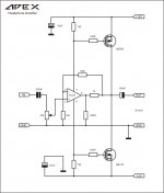
Not only the stability, I have a question about the distortion. The basic principle of this topology is the current drawn by opAmp is proportional to the input signal, and the resistors in series of the opAmp power supply generate proportional bias for the output devices which drives the load.
By my question is, how accurate is the power drawn by the opAmp proportional to the input signal? If it is not accurate, then output drive is not proportional to input signal means heavy distortion?
Thanks,
Routhun
By my question is, how accurate is the power drawn by the opAmp proportional to the input signal? If it is not accurate, then output drive is not proportional to input signal means heavy distortion?
Thanks,
Routhun
It all is within the feedback loop, so that shouldn't be too dramatic.
The opamp must be able to tolerate 1k2 of series resistance on the supplies though, which I guess means stability will depend heavily on the type used (ye olde TL07x isn't terribly critical AFAIK). A little too many ifs and buts for my taste, but YMMV.
The opamp must be able to tolerate 1k2 of series resistance on the supplies though, which I guess means stability will depend heavily on the type used (ye olde TL07x isn't terribly critical AFAIK). A little too many ifs and buts for my taste, but YMMV.
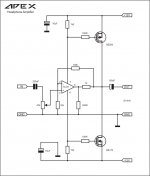
That's the "cascode" variation, which IMO stands a better chance of working well as the impedance seen by the opamp on its rails is much lower. As a further bonus, Vcc and Vee can be chosen higher than the opamp's maximum ratings, since the opamp is kept at lower supply voltages.
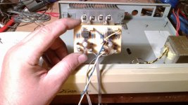
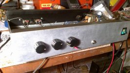
Today i started this...
Attachments
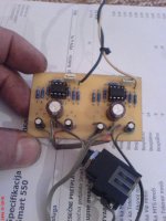
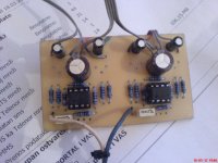
we will see,probably at monday...
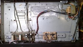
--->...over 1k2 in both rails of supply? I don´t know much about theory but i will try. I beleve in APEX designes just because i have built four of his ampolifiers (Ax12, NX16, HV23, G100) and a few other things (dc-overload protect + clip psu,ne555 protect,A-class shunt 2 x 24V,regulated PSU10,) and know about many other that work just fine (SR200, F100, AX14, A75, D14, auto range VU and clip indicator...) . That was enough for me to trust in all other of his designes so in this one too. I will try it these days,my job and my private obligatons don´t give me enough time just to put it inside the Standard preamp and to conect it to a +/-12V (to try it) ,it is allready assembled. When i finish it,i will try it with headphones and use it with an amplifier connected to an output just for others to hear how the amp sounds on a regular preamp and than on this head-amp. I don´t know no other way for other to hear it...
Are you sure you really want to load a TL07x with 220 ohms?
--->...over 1k2 in both rails of supply? I don´t know much about theory but i will try. I beleve in APEX designes just because i have built four of his ampolifiers (Ax12, NX16, HV23, G100) and a few other things (dc-overload protect + clip psu,ne555 protect,A-class shunt 2 x 24V,regulated PSU10,) and know about many other that work just fine (SR200, F100, AX14, A75, D14, auto range VU and clip indicator...) . That was enough for me to trust in all other of his designes so in this one too. I will try it these days,my job and my private obligatons don´t give me enough time just to put it inside the Standard preamp and to conect it to a +/-12V (to try it) ,it is allready assembled. When i finish it,i will try it with headphones and use it with an amplifier connected to an output just for others to hear how the amp sounds on a regular preamp and than on this head-amp. I don´t know no other way for other to hear it...
NOT WITHOUT 47k POT!
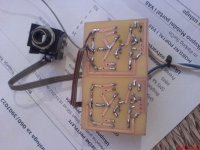
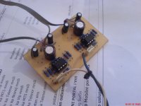
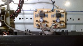
I have tried it today,but i made a big mistake because i didn´t put 47k trim.pot as it is shown in a schematics. I haven´t payed enough attention and that cost me output fets BS170,resistance of 47k trim.pot works along with adjusting volume as a connection of a TL071 negative feedback to the ground,so there was a big dc-offset at the output and my capacitor got very hot and almost exploded,luckely i have noticed that in time. Than i put MPSA92 / 42 instead BS250/170 AND IT WORKED! It sounds just fine but BJT´s are also getting very hot because they get too much base voltage. To get it to work in a BJT regime i beleive that 1k2 resistors in a power rails should be replaced with smaller resistance,and 220R load with a larger resistance. That is something that i don´t know to do quite well so i will rather buy a new pair of BS170 and do it again. What it matters is that this thing works,and that i have found a mistake that i made. Hope no one will do it after my experience!
I have tried it today,but i made a big mistake because i didn´t put 47k trim.pot as it is shown in a schematics. I haven´t payed enough attention and that cost me output fets BS170,resistance of 47k trim.pot works along with adjusting volume as a connection of a TL071 negative feedback to the ground,so there was a big dc-offset at the output and my capacitor got very hot and almost exploded,luckely i have noticed that in time. Than i put MPSA92 / 42 instead BS250/170 AND IT WORKED! It sounds just fine but BJT´s are also getting very hot because they get too much base voltage. To get it to work in a BJT regime i beleive that 1k2 resistors in a power rails should be replaced with smaller resistance,and 220R load with a larger resistance. That is something that i don´t know to do quite well so i will rather buy a new pair of BS170 and do it again. What it matters is that this thing works,and that i have found a mistake that i made. Hope no one will do it after my experience!
Attachments
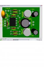
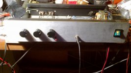
I promissed,so here it is...
No problem,it is in a link:
http://217.26.67.168/uploads/3/1/3115814/apex headphone amplifier top 44x37mm.pdf
http://217.26.67.168/uploads/3/1/3115814/apex headphone amplifier 44 x 37mm.pdf
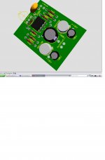
I did only one thing,i replaced 1k2 for a 820R to reduce the current through the headphone amplifier from 30mA to about 5mA per channel. It sounds...just like in this video: APEX HPA-2 headphone amplifier over APEX HV23 amplifier - YouTube
No problem,it is in a link:
http://217.26.67.168/uploads/3/1/3115814/apex headphone amplifier top 44x37mm.pdf
http://217.26.67.168/uploads/3/1/3115814/apex headphone amplifier 44 x 37mm.pdf
I did only one thing,i replaced 1k2 for a 820R to reduce the current through the headphone amplifier from 30mA to about 5mA per channel. It sounds...just like in this video: APEX HPA-2 headphone amplifier over APEX HV23 amplifier - YouTube
Attachments
- Status
- This old topic is closed. If you want to reopen this topic, contact a moderator using the "Report Post" button.
- Home
- Amplifiers
- Headphone Systems
- Mosfet Headphone Amp