Really surprised this has no responses! I saw this design on your site a while ago and now that I'm looking for a headphone amplifier for part of my DSP crossover unit I thought I'd look to see what feedback had been left on here.
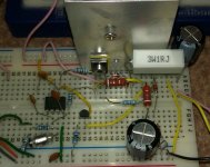
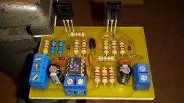
It's a really elegant design, quite simple, doesn't require too many parts (or expensive/rare ones) and offers great performance. I went ahead and built a prototype!

There's a few changes as I built using parts I have around. Op-amp is OPA227, Class-A biasing transistor is an MPSA18, R3 is only 4.7R, C2 is 150pF. Still, it worked first time with no issues apparent on my old 12MHz scope.
I only have 1 channel here so am running the left and right cans in parallel, a tough 16R load in fact! Still, bass is very deep and controlled, frequency response in general is the best I've heard from these, admittedly cheap, headphones.
I would like to get closer to 0R output impedance, and you say it is possible by just restricting the bandwidth? Should C1 be increased as well as C2? Perhaps R3 can come down to around 1R and R7 be replaced with an inductor+resistor parallel combination?
Also, it seems this design should be somewhat short circuit proof? Since max current is 300mA, provided the short isn't for too long and heatsinking is reasonable.
Anyhow, thanks for the design and I look forward to adding it to my next PCB layout alongside balanced line drivers. The plan is to go predominantly SMD.")
It's a really elegant design, quite simple, doesn't require too many parts (or expensive/rare ones) and offers great performance. I went ahead and built a prototype!
There's a few changes as I built using parts I have around. Op-amp is OPA227, Class-A biasing transistor is an MPSA18, R3 is only 4.7R, C2 is 150pF. Still, it worked first time with no issues apparent on my old 12MHz scope.
I only have 1 channel here so am running the left and right cans in parallel, a tough 16R load in fact! Still, bass is very deep and controlled, frequency response in general is the best I've heard from these, admittedly cheap, headphones.
I would like to get closer to 0R output impedance, and you say it is possible by just restricting the bandwidth? Should C1 be increased as well as C2? Perhaps R3 can come down to around 1R and R7 be replaced with an inductor+resistor parallel combination?
Also, it seems this design should be somewhat short circuit proof? Since max current is 300mA, provided the short isn't for too long and heatsinking is reasonable.
Anyhow, thanks for the design and I look forward to adding it to my next PCB layout alongside balanced line drivers. The plan is to go predominantly SMD.
Attachments
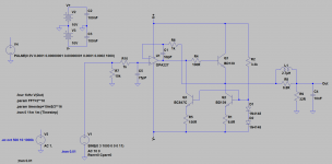
Well, it's quite easy to convert to zero Ohm output impedance but whether it's a good idea or not I am unsure. We lose the current clamp and so a short on the output will blow the output device. In terms of stability however it seems just fine using this inductor+resistor combination commonly seen on power amplifiers. The inductor is 25 turns of 22SWG copper, air core, 12mm diameter, DCR is approx 50mOhms.
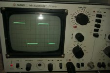
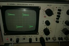
You can see the response to a 100kHz square wave with the output inductor and with it shorted. Load is 34Ohms resistive plus 10nF parallel capacitance. With the inductor in place I see no issues with stability even at the op-amp output and feedback (-) points.
Perhaps an over-current circuit can be designed which has minimal impact on output impedance? I will be using an SSR at the output anyhow for start-up mute, so anything which could detect excess current and trigger this would be neat.
Attachments
An RL seems a bit overkill for a circuit like this (I would've tried with just a Zobel first), but if you already have the parts and don't feel like sacrificing some performance for stability...
For short-circuit protection, you could insert some resistance in series with the collector of Q1. 10 ohms or so, depending on how much voltage swing you think you can afford to lose. The emitter follower will do its best not to let the output notice.
BTW, I would probably prefer a push-pull buffer, simply because it'll deliver twice as much output current in Class A for a given quiescent current (and can be pushed into AB if need be). It does have a somewhat higher parts count, of course.
I just noticed this now. Nice job Dr_EM.
How does if sound?
Here's the link to the original article for those that have not found it on my website
http://hifisonix.com/wordpress/wp-c...niversal-Small-Signal-Class-A-Buffer-V1.0.pdf
How does if sound?
Here's the link to the original article for those that have not found it on my website
http://hifisonix.com/wordpress/wp-c...niversal-Small-Signal-Class-A-Buffer-V1.0.pdf
Last edited:
I ended up implementing the design exactly as in your application since I decided the short circuit protection was really worthwhile in practice!
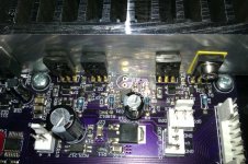
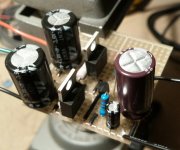
My implementation is nearly all SMD in fact and quite compact, but of course needs sizable heatsinking. It sounds flawless, never heard my headphones sound as good as with this but they are only quite cheap, Sennheiser HD205.
Bit of a poor photo but you can see it along the edge of this 8 channel buffer board, permanently connected to channels 7+8. Heatsink is just temporarily attached for lining up, of course all the devices shall be screwed in place later! The Class-A biasing transistor is now an SMT BC847 and op-amp is a humble OPA2134, OPA2227 also worked fine but the price went up before I ordered.
Thanks for the design!
Attachments
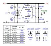
Novice question, can the circuit in figure 1 of the pdf be used as the final build, ( if I don't plan on driving more than 600 ohms ), or would it be better to use figure 13? I was confused over the use of the LM4562 dual op-amp as opposed to the LT1115 single. I guess the LT1115 was for simulation. Does it take two Lm4562's to make a stereo board? Thanks.
Of course you can use just one dual opamp for a stereo amp - the second half of the LM4562 as shown in Fig. 13 does absolutely nothing.
Fig. 13 is closer to real life otherwise. You'll just need to read the build notes carefully and decide which of the options you need or would like to have configurable. I assume you won't need output loading options, for example.
Fig. 13 is closer to real life otherwise. You'll just need to read the build notes carefully and decide which of the options you need or would like to have configurable. I assume you won't need output loading options, for example.
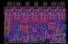
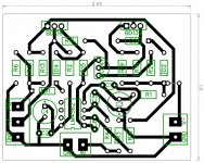
Well, I thought I would try to make a small pcb for this amp. Please point out any of the obvious mistakes. Honestly, there were a couple of things I was unsure of as far as the different configurations. I used figure 13 of the pdf. What I was going after, for my use anyway, was a headphone amp to drive ~40 ohm headphones. If I need to start over so be it, it's good practice. Thanks.
Attachments
Uh... one class A bias transistor for two channels?
Other than that, I don't really like power / grounding. Your power supply bypassing is pretty pointless - the small bypass caps should be at the opamp, not at the bigger caps. You could swap C2 and C4, while C1/C3 will be more difficult. Ideally, the path from the V+ pin over the bypass caps to the V- pin should be as short as possible; you can also add another cap directly from V+ to V-. In general, you have done your best to maximize power trace inductance - V+/V- run around the top of the board, and Gnd is on the bottom, giving a nice big loop. It would probably still work OK, since a SE Class A output stage doesn't have any nasty current pulses running around on the supplies (which then like to couple into the input circuitry and wreck HF THD in B/AB amps), but still...
Ground and power traces could be a smidgen wider, too.
Last edited:
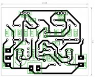
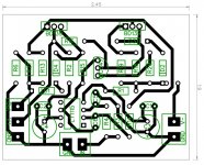
Thanks for the suggestions sgrossklass. I had already gone ahead and etched a board using the LT1115 opamp. It sounded good but was low volume. I've attached some pictures, one of the component numbers referenced to fig. 13 in Bonsai's pdf, the other one is the component values I ended up using based off of what I had. Since this is a mono board, I ended up just using the left side of my headphones, but what came out sounded really good, just quite. Because fig. 1 and fig. 13 are different, I am still confused about some of my values. I want to drive a pair of 50 ohm headphones. I think R6 may be the wrong value. I'll read the pdf a couple more times and see if I can get it.
Attachments

The LT1115 only appears to be stable at noise gains of 2 or higher, and it looks like the compensation pin is not connected anywhere, so it's not exactly ideal for a circuit like this.
Anyway, if the BD139s are getting warm, we'll assume that the circuit does its thing. Have you checked output DC offset? What sort of input level did you feed the circuit? Not sure what your headphones are, but if they're Sennheiser HD555/595 or something, they'd be plenty loud with a few dozen millivolts.
Anyway, if the BD139s are getting warm, we'll assume that the circuit does its thing. Have you checked output DC offset? What sort of input level did you feed the circuit? Not sure what your headphones are, but if they're Sennheiser HD555/595 or something, they'd be plenty loud with a few dozen millivolts.
Nice looking board Ripcord!
If you are feeding from a pre-mp deigned to give a nomib
Nail output of 1V (typically what is done today and will drive most SMPS to full power), you should provide an additional 3x to 4x gain ontop of this to the headphone amp. Why?
What you will find is that if you set the sound level on your volume pot the loudness between your speakers and headphone will be fairly matched. Of course, speaker and headphone sensitivities vary, but this is a good rule of thumb.
In my original write up, I showed an LM4562. These are unity gain stable, and you can use the first opamp to give the 3x to 4x gain I talk about.
I probably need to expand the write up to explicitly show a full class A SE HP amp circuit. On my list of to do actions!
Last edited:
Uh... one class A bias transistor for two channels?
Other than that, I don't really like power / grounding. Your power supply bypassing is pretty pointless - the small bypass caps should be at the opamp, not at the bigger caps. You could swap C2 and C4, while C1/C3 will be more difficult. Ideally, the path from the V+ pin over the bypass caps to the V- pin should be as short as possible; you can also add another cap directly from V+ to V-. In general, you have done your best to maximize power trace inductance - V+/V- run around the top of the board, and Gnd is on the bottom, giving a nice big loop. It would probably still work OK, since a SE Class A output stage doesn't have any nasty current pulses running around on the supplies (which then like to couple into the input circuitry and wreck HF THD in B/AB amps), but still...
Ground and power traces could be a smidgen wider, too.
Good suggestions!
Ok, I changed back to the LM4562 opamp and, as per sgrossklass suggestions, moved the small bypass caps closer to the pins. I can also add a cap between the +V and -V pins on the bottom side. I was actually using my phone as the source, (waiting for a power cord for my cd player). After I hooked up my headphones in mono it was quite a bit louder. My HP's are Fostex T20's, 50 ohm I think. Hopefully, Bonsai will make a dedicated class A HP amp out of this circuit. In the meantime sgrossklass, could you help me understand the rest of your suggestions for my layout?
Attachments
I'm using one of those little bench power supplies that does like 0-30vdc / 0-3amps. I then run that in to a virtual ground circuit that gives me ~plus and minus 17vdc. I got the idea from: http://www.diyaudio.com/forums/solid-state/234665-virtual-ground-regulated-rail-splitter.html
It works pretty good.
It works pretty good.
Attachments
I'm still using mine, right now in fact, on the ultra compact SMT PCB layout pictured on my last post and the performance is impressive every time. The improvement versus direct connection to even a good soundcard is very noticeable, it has surprised me 
My PCB has a solid ground plane and is very compact meaning short feedback and audio paths throughout. The compact layout was really because of limited board area but I'm pleased how it worked out.
My PCB has a solid ground plane and is very compact meaning short feedback and audio paths throughout. The compact layout was really because of limited board area but I'm pleased how it worked out.
- Status
- This old topic is closed. If you want to reopen this topic, contact a moderator using the "Report Post" button.
- Home
- Amplifiers
- Headphone Systems
- Universal Buffer/HP Amplifer