Apart from keeping power lines from output and twisting power, what else should I be tending to?
You shoud twist everything very tightly (not only power wires).
Yes, same thoughts here. And once you have it twisted you can either route the bundle as short as possible or along the edges of the case... makes for a much tidier appearance.
To my eyes the position of the Khozmo is quite ok since it's in line with the inlet filter...?
Hi MisterRogers,
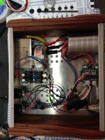
That is a great looking case and a very nice looking headphone amp!
As the others have mentioned, there is definitely some room for improvement on signal wiring and routing, and I'll try to highlight exactly what I would suggest.
The wiring part is always the most rushed (I know because I've been there and done that!) and it's too bad because it's probably the single most important aspect of the implementation.
People fret about what capacitors they should use, the effects of which come into play at -130dB. Meanwhile, sloppy wiring can cause mains hum (and harmonics) that are worse than -80dB, and spread across the entire audible spectrum, completely swamping the effects of pretty much anything else in the chain.
Here's what I would suggest:
1. All current carrying pairs MUST be tightly twisted together, and low level signal wires should also have an electrostatic shield.
2. All large signal AC wires (in this case mains wires and transformer secondary wires) should be kept as short as possible, and as far as possible from the signal carrying wires. They should also be tightly twisted in current carrying pairs.
3. Pay close attention to grounding. This can be very confusing in a bridge arrangement. Always remember that your ground wire should never carry signal in a truly differential arrangement.
Applying the above to your case, I would do the following:
1. Tightly twist the conductors running from XLR + and XLR - together running to the attenuator. Shield them with a grounded electrostatic shield. Conductive adhesive copper tape can work very well for this. Tape a layer down on the aluminum lid where you want to route your wires, position the wires over top and in the centre, and then tape another layer over top which effectively sandwiches the twisted conductors between two pieces of copper tape, and holds everything neat and tidy. Solder a lead from the copper tape to the GND pin on the XLR jack.
2. Tightly twist all the wires going into and out of the transformer in current carrying pairs. This means you need to look at the individual windings of the transformer and twist together the pairs of wires feeding each winding. Twisting together non-current carrying pairs (the way you twisted red-red and black-black) on the primary is not effective, and does not cancel the magnetic field generated by the conductors. They need to be twisted RED-BLACK and RED-BLACK for each primary winding on the dual primary transformer. Same applies to the secondary windings which are not twisted.
3. Cut the wires running to and from the transformer as short as possible, and route them as far as possible from the sensitive signal wires. Distance is your best friend!
4. Twist together the + and - conductors running from the attenuator to the input of the amp itself. Shield these with GND again using shielded twisted pair wires.
5. Twist the + and - output conductors from the amp output to the headphone jack.
6. Where possible, try and keep the left and right channels separated. If it comes down to prioritizing distance between channels and distance from the AC inlet and transformer, give preference to keeping the signal wires away from the AC inlet.
7. Twisting the wires from the PSU to the amps is a good idea, but they should be more tightly twisted.
Doing all the above will probably improve noise performance by between 10 and 20dB which will be easily audible with headphones, especially if they are high sensitivity.
If you want to attack the lowest hanging fruit first, the two 120V red and black wires running under the attenuator would be the best place to start. Cut the transformer leads down all the way and solder them directly to the AC mains filter outlet. If you can keep them less than 2" long and twist them tightly that will probably yield a significant improvement.
Next on the list would be tightly twisting the runs from the XLR input to the attenuator, even if you decide not to shield them. Twisted pairs will yield the bulk of the noise reducing benefits, while ES shielding is kinda like the cherry on top. Nice, but not strictly necessary")
Cheers,
Owen
That is a great looking case and a very nice looking headphone amp!
As the others have mentioned, there is definitely some room for improvement on signal wiring and routing, and I'll try to highlight exactly what I would suggest.
The wiring part is always the most rushed (I know because I've been there and done that!) and it's too bad because it's probably the single most important aspect of the implementation.
People fret about what capacitors they should use, the effects of which come into play at -130dB. Meanwhile, sloppy wiring can cause mains hum (and harmonics) that are worse than -80dB, and spread across the entire audible spectrum, completely swamping the effects of pretty much anything else in the chain.
Here's what I would suggest:
1. All current carrying pairs MUST be tightly twisted together, and low level signal wires should also have an electrostatic shield.
2. All large signal AC wires (in this case mains wires and transformer secondary wires) should be kept as short as possible, and as far as possible from the signal carrying wires. They should also be tightly twisted in current carrying pairs.
3. Pay close attention to grounding. This can be very confusing in a bridge arrangement. Always remember that your ground wire should never carry signal in a truly differential arrangement.
Applying the above to your case, I would do the following:
1. Tightly twist the conductors running from XLR + and XLR - together running to the attenuator. Shield them with a grounded electrostatic shield. Conductive adhesive copper tape can work very well for this. Tape a layer down on the aluminum lid where you want to route your wires, position the wires over top and in the centre, and then tape another layer over top which effectively sandwiches the twisted conductors between two pieces of copper tape, and holds everything neat and tidy. Solder a lead from the copper tape to the GND pin on the XLR jack.
2. Tightly twist all the wires going into and out of the transformer in current carrying pairs. This means you need to look at the individual windings of the transformer and twist together the pairs of wires feeding each winding. Twisting together non-current carrying pairs (the way you twisted red-red and black-black) on the primary is not effective, and does not cancel the magnetic field generated by the conductors. They need to be twisted RED-BLACK and RED-BLACK for each primary winding on the dual primary transformer. Same applies to the secondary windings which are not twisted.
3. Cut the wires running to and from the transformer as short as possible, and route them as far as possible from the sensitive signal wires. Distance is your best friend!
4. Twist together the + and - conductors running from the attenuator to the input of the amp itself. Shield these with GND again using shielded twisted pair wires.
5. Twist the + and - output conductors from the amp output to the headphone jack.
6. Where possible, try and keep the left and right channels separated. If it comes down to prioritizing distance between channels and distance from the AC inlet and transformer, give preference to keeping the signal wires away from the AC inlet.
7. Twisting the wires from the PSU to the amps is a good idea, but they should be more tightly twisted.
Doing all the above will probably improve noise performance by between 10 and 20dB which will be easily audible with headphones, especially if they are high sensitivity.
If you want to attack the lowest hanging fruit first, the two 120V red and black wires running under the attenuator would be the best place to start. Cut the transformer leads down all the way and solder them directly to the AC mains filter outlet. If you can keep them less than 2" long and twist them tightly that will probably yield a significant improvement.
Next on the list would be tightly twisting the runs from the XLR input to the attenuator, even if you decide not to shield them. Twisted pairs will yield the bulk of the noise reducing benefits, while ES shielding is kinda like the cherry on top. Nice, but not strictly necessary
Cheers,
Owen
Attachments
Just as an aside, there is a really fun experiment you can try at home to show the effectiveness of using twisted pairs.
Use a length of untwisted lamp cord to power a static load like a 60W light bulb. Lay two or three feet of the untwisted cord flat on the ground.
Make an XLR cable that has a normal XLR jack on one end and a straight pair of untwisted wires running a few feet to a 1k termination (connect + and -together with the resistor. This mimics the output of a preamp which has a 1k output impedance.
Connect that up to an amplifier powering an old speaker you're not worried about damaging.
Bring the untwisted signal wire into proximity with the untwisted power cable. Depending on the gain of the amplifier and the sensitivity of the loudspeaker, you should have a very loud 60Hz hum.
Now, twist just the power cable tightly together and repeat. Notice the very large reduction. Next, twist the signal wires together and repeat. Notice the even greater reduction. At this point, if the twists are tight enough, it should actually be difficult to get any 60Hz noise. Finally, untwist the power cable and do a final listen with just the signal wires twisted. Again notice the large reduction from the untwisted scenario.
The point of all this is the emphasize that twisting current carrying pairs helps reduce the amount of magnetic field emitted by a conductor, and also helps reduce the amount of magnetic field a conductor is susceptible to picking up. All of this happens because you're reducing the loop area of the current carrying pair by moving the current centroid of the outgoing current conductor more inline with the centroid of the returning current conductor, therefore cancelling or rejecting the magnetic fields generated by both.
Cheers,
Owen
Thanks Owen! I'll get to work on it. You're right - finishing off a build/wiring does tend to be the subject area that's received the least attention/study on my part. I tend to get caught up with testing/enjoying the efforts, accepting less than I should. This is an awesome breakdown of areas that should be addressed. I'll come back with an 'after' photo when I've applied your recommendations.
Excellent! I'd be curious to hear and see how everything goes
Just to be clear, I'm really not picking on your build in particular, It's just that your excellent pictures make it easy to point out what can be done to improve things, which will hopefully help everyone.
My current headphone implementation is sloppier looking than yours since it's lacking a case, and any other semblance of completion, so I'm not in a position to be judgmental
Cheers,
Owen
Absolutely no worries Owen; Didn't feel 'judged' at all. I have no illusions as to the 'correctness' of my builds. I'm always open to learning more, learning how to improve my builds. I'm listening to it right now, but there's nothing in me that thinks it's good enough I've said it before and at the risk of it sounding 'soapy' - I really appreciate the time that you and others take to instruct.
I've said it before and at the risk of it sounding 'soapy' - I really appreciate the time that you and others take to instruct.lol. Just emailed Neutrik and they basically told me that my 5mm front panel was possibly too thick for the Neutrik jack to lock. And that by removing the screw you might possibly loose the parts if your not careful (the latch is sprung loaded).
I'll have to find a thinner front panel.
I'll have to find a thinner front panel.
It's probably easier to buy the non-latched version of that connector...
Just a suggestion
Thanks! That will be the 3rd headphone jack for this amp.
That's a wild, outside of the box, thought Owen. You beat me to it ...
I'm well known for my wild crazy ideas

but will it blend?
The 5mm front panel or the Neutrik jack? My money is on the latter...
Thanks! That will be the 3rd headphone jack for this amp.
Plan twice buy once! It's cheaper than planning naught and buying thrice.
Besides, if you put the locking connector to the blender test, then it won't really be a waste now will it?
Cheers,
Owen
Sounds like a job for Front Panel Express: Front Panel Design Software and CAD Conversion Service
The non latching jacks like this - NMJ6HFD2-AU - Neutrik - should easily do 5mm ??
Have you already made a hole for the D socket? Why couldn't you mount the D socket anyway? I'm confused as to why this is an issue that needs a whole new front panel ...
Have you already made a hole for the D socket? Why couldn't you mount the D socket anyway? I'm confused as to why this is an issue that needs a whole new front panel ...
- Home
- Amplifiers
- Headphone Systems
- "The Wire" Ultra-High Performance Headphone Amplifier - PCB's