i knew there was something going on i didnt see properly, initially i thought the gain was 0.1, then it started to look weird and i gave up to go have a coffee and shower. note to self, never use words like definitely when your spidey senses are tingling. i didnt take into account the initial very basic 1 in the 1.1 on my initial glance, then 'over thunk' it  forgetting the buffer wrapped in the loop and thus the non inverting FB runs the other way towards ground from the output of the lme49990 through the buffer and back through the 1k0, departs to the inverting input with the 10k0 to ground, while the non-inverting input also flows straight through 1k0, splits off to the input while 10k0 goes to ground; so the symmetry works out with the 0.1 + 1
doh, now that cuts one down to size
forgetting the buffer wrapped in the loop and thus the non inverting FB runs the other way towards ground from the output of the lme49990 through the buffer and back through the 1k0, departs to the inverting input with the 10k0 to ground, while the non-inverting input also flows straight through 1k0, splits off to the input while 10k0 goes to ground; so the symmetry works out with the 0.1 + 1doh, now that cuts one down to size
Last edited:
qusp:
It's an easy mistake to make at a glance, so I wouldn't worry about it if I were you!
In fact, I actually built the first version as it was in the original schematic thinking everything was good, then when I measured it I got a gain of 1.81 and thought "WTF is going on here" before I realized that I had forgotten the +1 for the non-inverting setup.
I have tested the amp at a gain of 2 (and 1.8) and both work just as well, but I have yet to test at 3x or 4x. I'll get around to it eventually, but for now I would say that it's safe to build with gains up to 4x at least, and much beyond that there may be a need to increase Rf value along with the Rg value.
Cheers,
Owen
Regarding differential current drivers as an output stage:
ADSL line drivers can make for good audio devices, just consider the TPA6120A2 ("specified for audio" version of an ADSL counterpart).
But look how they do it. With dual single ended buffers in the feedback loop of a differential input stage. There are other approaches with all of the stages on the same die, too. But the principle stays the same.
So, no, even in that field it's done exactly the same way.
doesnt exist for audio, perhaps there are some RF or ADSL line drivers that provide a high current differential output
ADSL line drivers can make for good audio devices, just consider the TPA6120A2 ("specified for audio" version of an ADSL counterpart).
But look how they do it. With dual single ended buffers in the feedback loop of a differential input stage. There are other approaches with all of the stages on the same die, too. But the principle stays the same.
So, no, even in that field it's done exactly the same way.
Regarding differential current drivers as an output stage:
ADSL line drivers can make for good audio devices, just consider the TPA6120A2 ("specified for audio" version of an ADSL counterpart).
But look how they do it. With dual single ended buffers in the feedback loop of a differential input stage. There are other approaches with all of the stages on the same die, too. But the principle stays the same.
So, no, even in that field it's done exactly the same way.
sek, i'm really not quite sure what you are contesting. yet here you are again picking a line out of my post,m ignoring the rest and taking it out of context so you can more adequately disagree with it.
There is a scheme of an instrumentation amplifier with differential input and differential output, consisting of 2 SE-out opamps and 1 diff-out opamp.several reasons not to do that.
• for starters, an instrumentation amplifier usually has (perhaps by definition has to have) a differential input and a single ended output, how would this be useful for a balanced output amp? you would need to have 2 of them and supply it with a dual differential dac output to get a single balanced output.
Then, well, why the BAL-SE version uses 3 op-amps, when 1 op-amp already can convert balanced input to a single-end output? Or it can't?• 3 x opamps for starters doesnt make sense for balanced output unless performing a balanced-SE conversion, or if one of them was a differential I/O chip like the opa1632, noise performance with 2 series active elements will compound and be worse than the single diff chip. thermal and therefor common mode coupling/matching will be worse and thus noise performance will suffer again. this is handling 2 phases of the same channel, not 2 different channels. there is no benefit at all to using separate chips as could be argued (in a rather academic fashion) when talking about a left and right channel.
I understand about noise, but I don't think that at this level it's critical. I.e. -130dB or -160dB is anyways so low a noise it doesn't matter. While other moments may be significant. I've thought that 3 op-amp instrumentation amplifier circuits are used due to their high performance as in low distortion etc, and that was the reason to use it in The Wire?
Sorry for lame questions, I'm no expert in electronics.
That was in support of your point (of ADSL drivers not being better, as AFAIK they incorporate the same idea). Go figure.
hmm, well if i took you the wrong way (and it appears i did now reading back over it) my apologies, its what i'm used to you doing. i was confused because it seemed like you were countering me, without countering me.
but perhaps i was too jumpy there, i had been dealing with a bit of a situation we have going on here in Oz with a GB where the organiser appears to be pulling some kind of swifty, so was a bit wound up.
That's great news Wolfsin!
As a quick update, my giant order of 500 Nichicon FP caps arrived yesterday, and that has been holding up the shipment of all kits. I'll be going full bore this weekend to pack as many as I can, so the vast majority of people who have paid should see their packages ship out on Monday of next week.
Sorry to everyone for the delay, but this one was genuinely out of my control. Just the same, everyone who has paid will still get their stuff before the holidays.
On another note, it's looking a lot like the power amplifier payments and shipments will get pushed out to the new year since I don't foresee myself getting that project far enough along to accept payments and ship everything before the break. I'll see how things go this weekend and update early next week.
Cheers,
Owen
OK, qusp, my favorite DEMANDing curmudgeon
Hi Guyz,
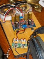
The right channel is down this afternoon for rework. My soldering skills are embarrasing. When I look at opc's work all I can think of is getting him to fly in for a ski vacation (complete with four bottomless glasses of microbrews) to teach me how to make solder flow.
The detail surpasses my other LME49600 preamp that uses 49710 rather than 1632. I have not yet taken the time to trim the balance to accomodate my unbalanced hearing but it is readily apparent how wonderful the Bal-Bal sounds.
Hi Guyz,
The right channel is down this afternoon for rework. My soldering skills are embarrasing. When I look at opc's work all I can think of is getting him to fly in for a ski vacation (complete with four bottomless glasses of microbrews) to teach me how to make solder flow.
The detail surpasses my other LME49600 preamp that uses 49710 rather than 1632. I have not yet taken the time to trim the balance to accomodate my unbalanced hearing but it is readily apparent how wonderful the Bal-Bal sounds.
Attachments
It's all about the flux.how to make solder flow.
Unless you're using lead free, which just won't flow all that well.
That's a Jung type ± regulator??
Have you tried the SuperTeddyReg? I heard about it a couple of weeks ago. The circuit details are 'open source' which is nice. Seems to favour lower than ultra low noise over line regulation and a few people said it sounded better to them than the 317/337 and the Jung type.
Last edited:
Wow! You work quickly!
I wasn't expecting anyone to have anything built up for at least a few weeks.
Congrats! It looks great.
As for the solder flowing, I'm all about using good solder and avoiding fine tip irons. Get lots of heat in quickly, and get out fast! I also don't worry about solder bridges and rely pretty heavily on solder wick to clean up if I do happen to make a mess. I find I do a much better job when I'm not worried about messing up.
I'm also all about leaded solder... which I strongly encourage in spite of the health related issues. Lead free solder is horrible to work with.
Thanks for getting pics up so quickly, I'm sure it will inspire others!
Cheers,
Owen
That's a Jung type ± regulator??
Honestly don't know. I purchased several pcbs a couple of years ago and have used it in the 15 and 18v configs. It is quite small and uses the case as a heatsink. It goes by many names and there is another DIYaudio thread where the BOM and schematic are posted.
Thanks for the soldering tip. S....Fun is out of stock on their water soluble flux right when I need it :-(
Do you have a favourite type and thickness?...using good leaded solder
I have the thicker Wonder solder and a tiny bit of thin Cardas that came with some Cardas plugs last year. The old wonder solder of years ago seemed to flow a bit more, the last reel I bought seems to oxidise too quickly.
They both flow quite well compared to some other stuff I've seen friends attempt to use. That was awful stuff, seemed to have very little flux in it's core. Now I supply them all with a metre of Wonder solder when they need it and their soldering is now much better. That's really what I meant by flux, a solder with a good amount of it in and make sure to get loads of it onto the joint and not just get dry solder on there. But I have used a flux pen to apply a bit onto an area first and the solder flowed really well. I've not had cause to do it but I saw a short video recommending to pre flux the pads when about to solder a very many pin surface mount chip.
Last edited:
Wow! You work quickly!
I wasn't expecting anyone to have anything built up for at least a few weeks.
Congrats! It looks great.
Thanks. Being of full retardation age I have the time -- just not the speed. I am also building a JC-80 with help from Mr. JC himself and can hardly wait to compare the best of the old and new. Thanks for the soldering tips in addition to the awsome design.
Have you tried the SuperTeddyReg?
No, but I will check it out. I am considering a Kubota for use as part of the JC-80 project I am working on. Please send a pointer.
Last edited:
- Home
- Amplifiers
- Headphone Systems
- "The Wire" Ultra-High Performance Headphone Amplifier - PCB's