
I want to pay..when do i pay?
-joe
See post #695:
Hi Guys,
No payments yet, as I still need to test all the boards on arrival.
Here's the schedule:
- GB closes Sunday September 25th (this Sunday)
- Place PCB order Monday September 26th
- Boards arrive two weeks later on Monday October 10th
- One week to assemble and test all variations brings us to October 21st
- Payments will start to be accepted October 21st and boards/kits will ship out the following week.
I hope that clarifies things!
Cheers,
Owen
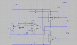
Hello, I'm curious about the design techniques used to design the PCB.
Is the PCB designed with a center ground plane or a star ground?
what is the power/signal/plan distribution like?
thanks.
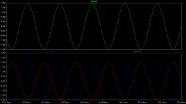
EDIT: Also if this is not asking too much, can someone show me the square wave response of the amplifier?
THANKS!
Is the PCB designed with a center ground plane or a star ground?
what is the power/signal/plan distribution like?
thanks.
EDIT: Also if this is not asking too much, can someone show me the square wave response of the amplifier?
THANKS!
Last edited:
Owen -
What are the dimensions of the PSU?
An image of the layout would be nice too.
Thanks
Hi,
Owen,
According to your schedule PCBs are now in production - could you please the finally specify board dimensions (with mounting holes location) and layout please?
rgds,
jacek
Anticipation iz makin'me . . . Short of working on a case there is little to do to cut the anxiety called forth by anticipation so, Jacek, if you need to build it now, just build it BIG
I am eager to build it too. Everything iz procured, powsupp iz ready, so I lashed up a way to A-B compare the bal-bal to a pair of bridged LME49600 boards, each using a pair on the push and a pair on the pull. Thinking about test now iz a good way to get ready even if you expect, as I do, the null outcome. Also take the time to think thru the cabling now to avoid the last minute rush to that 'first listen'. When I first connected the bridging noted above I used blocking caps that, upon reflection, were not needed and misled me to an unwarranted disappointment.
I am eager to build it too. Everything iz procured, powsupp iz ready, so I lashed up a way to A-B compare the bal-bal to a pair of bridged LME49600 boards, each using a pair on the push and a pair on the pull. Thinking about test now iz a good way to get ready even if you expect, as I do, the null outcome. Also take the time to think thru the cabling now to avoid the last minute rush to that 'first listen'. When I first connected the bridging noted above I used blocking caps that, upon reflection, were not needed and misled me to an unwarranted disappointment.
i hope in this coming design owen will allocate space to mounth the volume control on pcb
The layout has already been posted (the se-se version anyways) in post #658.
No space for a pot it would seem.
Unless you are referring to something else?
space for a pot is not a good idea for a gb, everyone has different favorites for such things, for instance i dont use one at all
i see..
i wanna ask a question, is it a good implementation to put the wire as pre amp? i'm planning to combine this with my LM3875 gainclone (gain 33)
Owen, I don't know whether I'm just misinterpreting somehing (or maybe I'm just plain stupid ), but shouldn't the price list for the PSU have 2 of each regulator? The schematic contains U19-22 and you list them all in the price list, but the quantities for LM317/337 is only one each.
Cheers
), but shouldn't the price list for the PSU have 2 of each regulator? The schematic contains U19-22 and you list them all in the price list, but the quantities for LM317/337 is only one each.Cheers
i see..
i wanna ask a question, is it a good implementation to put the wire as pre amp? i'm planning to combine this with my LM3875 gainclone (gain 33)
perhaps, but do you really NEED a preamp? it doesn't have any facility for multiple inputs and as written doesn't actually have any gain (although this is easily achieved)
Looks like the BAL-BAL board can also make a great SE-to BAL converter by grounding one input and changing the feedback resistors to 2K.
Attachments
Last edited:
Hi Guys,
Sorry for the lack of responses lately, it has been a pile of work getting everything together, and it was either an hour on here fielding questions, or an hour doing testing and board layout, and I know everyone is looking forward to finally getting boards and kits.
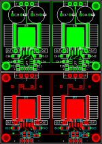
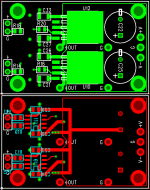
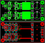
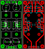
I finally have all the completed layouts to post along with finished sizes. Each image has the top and bottom layer shown, but the centre ground layer is not shown (it's pretty boring anyways). These are the finished layouts that were sent in for fabrication, so it's safe to use them for chassis selection, planning etc...
Here are the finished sizes:
BAL-BAL = 2.325" x 1.625"
SE-SE = 1.825" x 1.150"
BAL-SE = 2.325" x 1.625"
PSU = 2.525" x 1.150"
All the boards have 4 mounting points intended for #4 bolts and standoffs. On each of the boards, the holes are located 0.125" inset from each corner. The only exception is the SE-SE board which has two of the bolt holes offset by 0.2" from the edge in the x direction. It should be obvious from the images which two bolt holes are different.
I'll field the buildup of questions later today. The boards are currently in production, and I should have them early next week. I am indeed running behind, and I apologize to those who are eager to get their boards. I should be accepting payments and sending boards out shortly.
An updated list is also attached.
Cheers,
Owen
Sorry for the lack of responses lately, it has been a pile of work getting everything together, and it was either an hour on here fielding questions, or an hour doing testing and board layout, and I know everyone is looking forward to finally getting boards and kits.
I finally have all the completed layouts to post along with finished sizes. Each image has the top and bottom layer shown, but the centre ground layer is not shown (it's pretty boring anyways). These are the finished layouts that were sent in for fabrication, so it's safe to use them for chassis selection, planning etc...
Here are the finished sizes:
BAL-BAL = 2.325" x 1.625"
SE-SE = 1.825" x 1.150"
BAL-SE = 2.325" x 1.625"
PSU = 2.525" x 1.150"
All the boards have 4 mounting points intended for #4 bolts and standoffs. On each of the boards, the holes are located 0.125" inset from each corner. The only exception is the SE-SE board which has two of the bolt holes offset by 0.2" from the edge in the x direction. It should be obvious from the images which two bolt holes are different.
I'll field the buildup of questions later today. The boards are currently in production, and I should have them early next week. I am indeed running behind, and I apologize to those who are eager to get their boards. I should be accepting payments and sending boards out shortly.
An updated list is also attached.
Cheers,
Owen
Attachments
- Home
- Amplifiers
- Headphone Systems
- "The Wire" Ultra-High Performance Headphone Amplifier - PCB's