I don't see why regular volume control on the input shouldn't work with The Wire. In a fully balanced amp a balanced volume control on the input side would probably overcomplicate things a bit, though, as a four-gang precision pot is large, expensive and maybe even hard to come by.
I used to post an approach for a volume control in a (fully) balanced headphone amp a while ago. Apparently not too many people are interested in fully balanced configurations, though. The approach shown in that thread preserves the balance of both level and impedance, introduces no common mode error and only requires one of the common pots of reasonable quality (as it isn't part of the "signal path").
Take a look at fig. 22 (p. 14) in TI's Differential Operational Amplifier Circuit Collection. It features a fully differential opamp (such as the THS4130/OPA1632) and two output buffers (such as BUF634/LME49600), one per differential leg, respectively.
If you take a look at The Wire in it's balanced in and balanced out version (p. 3) you see exactly that signal flow, just with a global feedback loop around both the opamp and the buffer.
In my above thread I (currently) favor the topology from TI's circuit collection (local feedback to both the opamp and the buffers, respectively), but only as a starting point. The Wire still has all the features that enable a differential (shunt type) attenuator between opamp and buffer stage.
With the signal being fully differential, no bad things would happen if it were to be extended towards a pot using symmetrical, shielded, quality wire.
Finally, I agree that the amount of feedback itself should not be hampered with, as pots usually fail open, i.e. lose contact during noisy bumping (or oxidizing).
Cheers,
Sebastian.
Hi Guys,
qusp:
Sorry, I didn't mean to scold, I just wanted to be clear about this particular amplifier and its implementation. I'm not saying the technique wouldn't work, (especially with careful implementation on a lower BW amplifier) I'm just saying that it's not suitable for use in this circuit, and I generally don't agree with the idea.
sek:
You're absolutely correct, a normal volume control is perfectly fine for this application. If it's SE input, use an SE attenuator, and if it's differential, use a differential attenuator. It's that simple. I'm not sure why people got their panties all in a knot about this.
If you use differential connections and your system is differential throughout, then you owe it to yourself to have a good differential attenuator, be it a passive pot, or an active preamp like a BOSOZ.
I could certainly look into implementing something like that, as I see no reason why it wouldn't work. It does introduce four extra resistors into the signal path, however, plus the common shunt element. The idea of running flying leads all the way back to a pot on the front panel from that part of the circuit still makes me very skeptical though. It's not just noise, but also stray capacitance and inductance.
As soon as you start opening up sensitive parts of the circuit like that to the builder, you open a Pandora's Box of possible problems arising from poor implementation and sloppy wiring.
If the LME49600 was to be pulled out of the feedback loop it would probably be less sensitive, but I'm not entirely sure how it would perform outside the loop. I suppose it's something I could try out on my test board.
Thanks for the input and the great links! I'll give it a close look and let you know.
Cheers,
Owen
qusp:
Sorry, I didn't mean to scold, I just wanted to be clear about this particular amplifier and its implementation. I'm not saying the technique wouldn't work, (especially with careful implementation on a lower BW amplifier) I'm just saying that it's not suitable for use in this circuit, and I generally don't agree with the idea.
sek:
I don't see why regular volume control on the input shouldn't work with The Wire.
You're absolutely correct, a normal volume control is perfectly fine for this application. If it's SE input, use an SE attenuator, and if it's differential, use a differential attenuator. It's that simple. I'm not sure why people got their panties all in a knot about this.
In a fully balanced amp a balanced volume control on the input side would probably overcomplicate things a bit, though, as a four-gang precision pot is large, expensive and maybe even hard to come by.
If you use differential connections and your system is differential throughout, then you owe it to yourself to have a good differential attenuator, be it a passive pot, or an active preamp like a BOSOZ.
I used to post an approach for a volume control in a (fully) balanced headphone amp a while ago. Apparently not too many people are interested in fully balanced configurations, though. The approach shown in that thread preserves the balance of both level and impedance, introduces no common mode error and only requires one of the common pots of reasonable quality (as it isn't part of the "signal path").
Take a look at fig. 22 (p. 14) in TI's Differential Operational Amplifier Circuit Collection. It features a fully differential opamp (such as the THS4130/OPA1632) and two output buffers (such as BUF634/LME49600), one per differential leg, respectively.
If you take a look at The Wire in it's balanced in and balanced out version (p. 3) you see exactly that signal flow, just with a global feedback loop around both the opamp and the buffer.
In my above thread I (currently) favor the topology from TI's circuit collection (local feedback to both the opamp and the buffers, respectively), but only as a starting point. The Wire still has all the features that enable a differential (shunt type) attenuator between opamp and buffer stage.
With the signal being fully differential, no bad things would happen if it were to be extended towards a pot using symmetrical, shielded, quality wire.
I could certainly look into implementing something like that, as I see no reason why it wouldn't work. It does introduce four extra resistors into the signal path, however, plus the common shunt element. The idea of running flying leads all the way back to a pot on the front panel from that part of the circuit still makes me very skeptical though. It's not just noise, but also stray capacitance and inductance.
As soon as you start opening up sensitive parts of the circuit like that to the builder, you open a Pandora's Box of possible problems arising from poor implementation and sloppy wiring.
If the LME49600 was to be pulled out of the feedback loop it would probably be less sensitive, but I'm not entirely sure how it would perform outside the loop. I suppose it's something I could try out on my test board.
Thanks for the input and the great links! I'll give it a close look and let you know.
Cheers,
Owen
thanks for the post sek, I guess my powers of description are failing me, it was something like this i was trying to get accross, using a 2 channel pot in the feedback loop for a balanced control was how i started many pages ago, perhaps inside the loop isnt entirely accurate, even though its effect is certainly inside the loop. relays prevent flying signal leads....... not straight forward to swap into a regular design thouigh
Last edited:
I think that I'll try building my SE->SE up in an Altoids can using a 6W DC-DC converter instead of batteries. Not portable, but nice and small.
This Murata 12VDC (in) with dual isolated +/-15VDC (out) at 200mA per channel
NCS6D1215C converter at Mouser
Datasheet PDF at Murata
Switching frequency is way up at 180kHz which shouldn't interfere with the audio. I'll just feed it with a 12VDC 600mA or 24VDC 300mA wall wart. The unit is only 1.26" x 0.787" leaving plenty of room for a DC power jack, the two audio jacks, and a switch.
Should be a fun build.")
This Murata 12VDC (in) with dual isolated +/-15VDC (out) at 200mA per channel
NCS6D1215C converter at Mouser
Datasheet PDF at Murata
Switching frequency is way up at 180kHz which shouldn't interfere with the audio. I'll just feed it with a 12VDC 600mA or 24VDC 300mA wall wart. The unit is only 1.26" x 0.787" leaving plenty of room for a DC power jack, the two audio jacks, and a switch.
Should be a fun build.
Last edited:
Hi,
thanks for the quick feedback.
Yep, introducing the shunt would be the very point of that idea.
The leads should of course ideally be of reasonable quality. As long as they maintain symmetry (due to twisted and rigid cable construction) they would maintain impedance matching as a balanced pair.
Stray capacitance would dominate the shunting path, inductance the series path, respectively. All in all, that would potentially limit bandwith but not reduce phase margin within the loop.
Actually, if you look at fig. 4 (p. 9) of the BUF634 datasheet, you'll see that TI actually recommends introducing a shunting capacitance in case you worry about stability with high speed components.
That's a valid concern! This problem can be adressed by adding an input buffer stage, though, i.e. an instrumentation stage (with the shunt attenuator in front of it) or another OPA1632 (with the shunt attenuator behind it).
I'm not really advocating this approach as the only valid solution, but I'd prefer a solution that would integrate well with The Wire (instead of leaving this rather difficult problem to the user).
You're right with this statement, but at the same time you kind of shift the design issue away. People seem to demand it. *hint*hint*
Pulling it out of the loop doesn't feel right at first glance, but those parts are diamond buffers, after all.
Personally, I'd rahter go as far as bringing the balanced opamp and the output stage into a SuSy configuration (with dedicated common mode feedback as per users wensan and okapi, see over here), althoug this would require differential amplifiers in the output section (like the TPA6120 I proposed). But that's another project.
The differential shunt is not new, even here on DIYAudio the topic has been had before. I've never tried it myself, though. We'll see, maybe I also get around to doing it in the next couple of weeks.
Thanks,
Sebastian.
thanks for the quick feedback.
I could certainly look into implementing something like that, as I see no reason why it wouldn't work. It does introduce four extra resistors into the signal path, however, plus the common shunt element.
Yep, introducing the shunt would be the very point of that idea.
The idea of running flying leads all the way back to a pot on the front panel from that part of the circuit still makes me very skeptical though. It's not just noise, but also stray capacitance and inductance.
The leads should of course ideally be of reasonable quality. As long as they maintain symmetry (due to twisted and rigid cable construction) they would maintain impedance matching as a balanced pair.
Stray capacitance would dominate the shunting path, inductance the series path, respectively. All in all, that would potentially limit bandwith but not reduce phase margin within the loop.
Actually, if you look at fig. 4 (p. 9) of the BUF634 datasheet, you'll see that TI actually recommends introducing a shunting capacitance in case you worry about stability with high speed components.
As soon as you start opening up sensitive parts of the circuit like that to the builder, you open a Pandora's Box of possible problems arising from poor implementation and sloppy wiring.
That's a valid concern! This problem can be adressed by adding an input buffer stage, though, i.e. an instrumentation stage (with the shunt attenuator in front of it) or another OPA1632 (with the shunt attenuator behind it).
I'm not really advocating this approach as the only valid solution, but I'd prefer a solution that would integrate well with The Wire (instead of leaving this rather difficult problem to the user).
If you use differential connections and your system is differential throughout, then you owe it to yourself to have a good differential attenuator
You're right with this statement, but at the same time you kind of shift the design issue away. People seem to demand it. *hint*hint*
If the LME49600 was to be pulled out of the feedback loop it would probably be less sensitive, but I'm not entirely sure how it would perform outside the loop. I suppose it's something I could try out on my test board.
Pulling it out of the loop doesn't feel right at first glance, but those parts are diamond buffers, after all.
Personally, I'd rahter go as far as bringing the balanced opamp and the output stage into a SuSy configuration (with dedicated common mode feedback as per users wensan and okapi, see over here), althoug this would require differential amplifiers in the output section (like the TPA6120 I proposed). But that's another project.
thanks for the post sek, I guess my powers of description are failing me, it was something like this i was trying to get accross, using a 2 channel pot in the feedback loop for a balanced control was how i started many pages ago, perhaps inside the loop isnt entirely accurate, even though its effect is certainly inside the loop. relays prevent flying signal leads....... not straight forward to swap into a regular design thouigh
The differential shunt is not new, even here on DIYAudio the topic has been had before. I've never tried it myself, though. We'll see, maybe I also get around to doing it in the next couple of weeks.
Thanks,
Sebastian.
]
nope, i just couldnt think of the correct terminology. i had also funnily enough come across it in that same app note you quoted a few posts up when looking for differential bass control for a friend who was wanting to build a balanced m3 headamp and trying to avoid the expense and difficulty of matching high quality film caps across +/-
The differential shunt is not new, even here on DIYAudio the topic has been had before. I've never tried it myself, though. We'll see, maybe I also get around to doing it in the next couple of weeks.
Thanks,
Sebastian.
nope, i just couldnt think of the correct terminology. i had also funnily enough come across it in that same app note you quoted a few posts up when looking for differential bass control for a friend who was wanting to build a balanced m3 headamp and trying to avoid the expense and difficulty of matching high quality film caps across +/-
Hi qusp,
Slightly OT, but still out of curiosity: What's a balanced M3?
The concept of the M3 is that of "amplifying" and buffering the common output ground in the same way the left and right channel outputs are amplified and buffered.
When making the outputs fully balanced, doesn't that render the idea of a buffered ground pointless? And isn't the output still not fully balanced (but instead simply doubled, making one independent channel per output phase)?
Just curious,
Sebastian.
PS: The idea of a THS4130/OPA1632 with buffers in the inverting/noninverting feedback loop is something entirely different, anyway.
nope, i just couldnt think of the correct terminology. i had also funnily enough come across it in that same app note you quoted a few posts up when looking for differential bass control for a friend who was wanting to build a balanced m3 headamp and trying to avoid the expense and difficulty of matching high quality film caps across +/-
Slightly OT, but still out of curiosity: What's a balanced M3?
The concept of the M3 is that of "amplifying" and buffering the common output ground in the same way the left and right channel outputs are amplified and buffered.
When making the outputs fully balanced, doesn't that render the idea of a buffered ground pointless? And isn't the output still not fully balanced (but instead simply doubled, making one independent channel per output phase)?
Just curious,
Sebastian.
PS: The idea of a THS4130/OPA1632 with buffers in the inverting/noninverting feedback loop is something entirely different, anyway.
it is rather pointless when u populate the ground channel yeah i only used 2 channels out of each board in the only 'balanced' m3 i ever built. but as you say what i ended up with was not really an m3. i toyed with the idea of populating the buffered ground only for an optional SE output, but didnt bother in the end. i simply used a sigma22 and real ground for psu and skipped Vground and the cap multiplier
the board i was talking about though was an adaption of the cct using the differential opa for input, not an actual m3
anyway back to 'the wire' i'm getting the first gen board ready in its home for the Sydney headfi meet this coming weekend, should be some good feedback. its got some stiff competition at the table i'm at though, i'll be also feeding a friends KGSS with BSHE adapter board and STAX O2 with the titan usb->Ackodac AKD12P->D1
i only used 2 channels out of each board in the only 'balanced' m3 i ever built. but as you say what i ended up with was not really an m3. i toyed with the idea of populating the buffered ground only for an optional SE output, but didnt bother in the end. i simply used a sigma22 and real ground for psu and skipped Vground and the cap multiplierthe board i was talking about though was an adaption of the cct using the differential opa for input, not an actual m3
anyway back to 'the wire' i'm getting the first gen board ready in its home for the Sydney headfi meet this coming weekend, should be some good feedback. its got some stiff competition at the table i'm at though, i'll be also feeding a friends KGSS with BSHE adapter board and STAX O2 with the titan usb->Ackodac AKD12P->D1
Last edited:
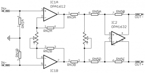
opc said:I could certainly look into implementing something like that, as I see no reason why it wouldn't work.sek said:I used to post an approach for a volume control in a (fully) balanced headphone amp a while ago.
I gave the idea a try in a form that can be adapted to The Wire (see attached pic). I describe it in the abovementioned thread and even show a prototype pic.
It works as expected, although my implementation lacks any kind of devotion to detail. I didn't listen to it, as I have no cheap phones that I'd like to waste on a lousy proof of concept, but it scopes just fine.
Cheers,
Sebastian.
Attachments
Hi sek,
That's essentially just an active balanced preamp stage added onto the existing BAL-BAL circuit isn't it?
A big bonus of "The Wire" as a concept is that it's scaled down to the most basic level of simplicity, and does only what it's supposed to do very very well as a result.
I personally use the output of a Buffalo II DAC to drive the discrete I/V stage I designed a while back, and feed that directly into "The Wire". In that setup there is no need for a volume control since the one implemented in the digital domain on the Buffalo is more of less perfect and requires nothing at all in the signal path.
What you have there would require me to add an extra gain stage and 12 components into the mix. Even if you didn't have the luxury of the volume control on the DAC, wouldn't you rather just use a good stepped attenuator with 0.1% resistors? That's only two parts in the signal chain, and no active devices at all.
Don't get me wrong... I do like the idea you've come up with, and it looks like it works perfectly, it's just not really a good fit with what I'm trying to do here.
Overall, there's no substitute for simplicity. If you want a volume control that matches well with "The Wire", then either get yourself a Buffalo II DAC, or a good quality balanced stepped attenuator! You can build a decent stepped attenuator yourself for less than $100, and you'll have it for the rest of your life. Trust me... it's money and time well spent.
Cheers,
Owen
Hi Owen,
The output stage resembles that of the BAL-BAL circuit (although I prefer the BUF634 over the LME49600) and is basically a mixture of fig.2, p.3 as well as fig.22, p.14 in TI's Differential Op-Amp Circuit Collection and fig.4, p.7 in the INA163 datasheet (which in turn is basically your BAL-SE).
But as both gain and interstage impedances change, the calculation is entirely different from the BAL-BAL: adjustable input stage gain (to account for headphone sensitivity), varying attenuator impedance (in case of a pot), output stage with gain (to make up for attenuator loss).
I've refrained from using the TPA6210A2/THS6012 and changed focus to the BUF634/LME49600 after reading up on issues with the former in the FiiO E9 and QRV09 into low impedance headphones. My current feature set is represented by Violectric's HPA-V181. I'd like to improve on that one by going all balanced throughout.
I understand you went all digital, as far as source material is concerned. But even when doing so, others might use different I/V and filter stages.
Let's not forget that the BAL-BAL circuit has the OPA1632 directly on the input (unlike your BAL-SE, where you also employ an instrumentation amplifier). For people using a different setup, would it sound and behave the same on high impedance sources as well as low impedance sources?
How come?
It's basically like merging SE-BAL with BAL-BAL. Plus an attenuator (which is the whole culprit). Assuming it works this way, of course (still not fully tested).
If you account for power supply bypassing, there's of course some increase in parts count, but I assume you were referring to signal circuitry.
A differential buffer consisting of something like OPA1612/OPA2211/LME49990 in a gain-of-one configuration doesn't bother me, especially if it solves problems. Add to that the proper use of high precision resistor networks (+/-0.05% tolerance, +/-7.5ppm drift) in a tight, good PCB layout and the amount of error introduced quickly becomes a matter of belief.
And to answer your question: no, I rather wouldn't like to use two balanced attenuators (stereo) if I can substitute it with one unbalanced stereo attenuator and a high quality buffer stage.
Totally. That's why this project of yours should be carried on the way you like. I was basically just wondering why volume control wasn't taken into consideration at all, seeing that a couple of people asked for it. But as it's a dedicated stage in an existing setup (and not a headphone amplifier, as the thread title would suggest), then there's no reason to compromise on your simplistic approach.
Don't get me started on the "there's always a simple solution" discussion.
Otherwise we would have to discuss why the balanced stepped attenuator you propose shouldn't be replaced with, say, an MPC507...
The Sabre DACs (and what Brian and Russ do with them in the Buffalo II and soon to be released Buffalo III) is certainly a kind of a milestone. But not everyone solely listens to digital content.
Which leaves us with the balanced stepped attenuator. Well, my idea is to reduce the requirement from a balanced to an unbalanced attenuator (stepped or pot, if possible) while still preserving all the benefits.
But I'm getting carried away.
Cheers,
Sebastian.
That's essentially just an active balanced preamp stage added onto the existing BAL-BAL circuit isn't it?
The output stage resembles that of the BAL-BAL circuit (although I prefer the BUF634 over the LME49600) and is basically a mixture of fig.2, p.3 as well as fig.22, p.14 in TI's Differential Op-Amp Circuit Collection and fig.4, p.7 in the INA163 datasheet (which in turn is basically your BAL-SE).
But as both gain and interstage impedances change, the calculation is entirely different from the BAL-BAL: adjustable input stage gain (to account for headphone sensitivity), varying attenuator impedance (in case of a pot), output stage with gain (to make up for attenuator loss).
I've refrained from using the TPA6210A2/THS6012 and changed focus to the BUF634/LME49600 after reading up on issues with the former in the FiiO E9 and QRV09 into low impedance headphones. My current feature set is represented by Violectric's HPA-V181. I'd like to improve on that one by going all balanced throughout.
I personally use the output of a Buffalo II DAC to drive the discrete I/V stage I designed a while back, and feed that directly into "The Wire". In that setup there is no need for a volume control
I understand you went all digital, as far as source material is concerned. But even when doing so, others might use different I/V and filter stages.
Let's not forget that the BAL-BAL circuit has the OPA1632 directly on the input (unlike your BAL-SE, where you also employ an instrumentation amplifier). For people using a different setup, would it sound and behave the same on high impedance sources as well as low impedance sources?
What you have there would require me to add an extra gain stage and 12 components into the mix.
How come?
It's basically like merging SE-BAL with BAL-BAL. Plus an attenuator (which is the whole culprit). Assuming it works this way, of course (still not fully tested).
If you account for power supply bypassing, there's of course some increase in parts count, but I assume you were referring to signal circuitry.
Even if you didn't have the luxury of the volume control on the DAC, wouldn't you rather just use a good stepped attenuator with 0.1% resistors? That's only two parts in the signal chain, and no active devices at all.
A differential buffer consisting of something like OPA1612/OPA2211/LME49990 in a gain-of-one configuration doesn't bother me, especially if it solves problems. Add to that the proper use of high precision resistor networks (+/-0.05% tolerance, +/-7.5ppm drift) in a tight, good PCB layout and the amount of error introduced quickly becomes a matter of belief.
And to answer your question: no, I rather wouldn't like to use two balanced attenuators (stereo) if I can substitute it with one unbalanced stereo attenuator and a high quality buffer stage.
Don't get me wrong... I do like the idea you've come up with, and it looks like it works perfectly, it's just not really a good fit with what I'm trying to do here.
Totally. That's why this project of yours should be carried on the way you like. I was basically just wondering why volume control wasn't taken into consideration at all, seeing that a couple of people asked for it. But as it's a dedicated stage in an existing setup (and not a headphone amplifier, as the thread title would suggest), then there's no reason to compromise on your simplistic approach.
Overall, there's no substitute for simplicity.
Don't get me started on the "there's always a simple solution" discussion.
Otherwise we would have to discuss why the balanced stepped attenuator you propose shouldn't be replaced with, say, an MPC507...
If you want a volume control that matches well with "The Wire", then either get yourself a Buffalo II DAC, or a good quality balanced stepped attenuator!
The Sabre DACs (and what Brian and Russ do with them in the Buffalo II and soon to be released Buffalo III) is certainly a kind of a milestone. But not everyone solely listens to digital content.
Which leaves us with the balanced stepped attenuator. Well, my idea is to reduce the requirement from a balanced to an unbalanced attenuator (stepped or pot, if possible) while still preserving all the benefits.
But I'm getting carried away.
Cheers,
Sebastian.
Last edited:
where is that file located ?
(I may need to update my desired quantity as well)
http://www.diyaudio.com/forums/head...-headphone-amplifier-pcbs-53.html#post2613496
Is it only me or other experience the same?
I could not properly open Owen's "THE WIRE - THREE BOARD - 4.pdf" file.
The text is always missing, with the message that Verdana font is not available, which is not true since my PC has Verdana installed.
Try to update or re-install your Acrobat Reader app
I've tried right now and it's Ok.
Cheers
Try to update or re-install your Acrobat Reader app
I've tried right now and it's Ok.
Cheers
I see... thanks...
- Home
- Amplifiers
- Headphone Systems
- "The Wire" Ultra-High Performance Headphone Amplifier - PCB's