boards arrived!! great work as usual opc, neat and OMG so small! the pictures are misleading. they are small enough to be easily integrated into any project just stuck to the wall near the output jacks and probably even tapping a supply thats already there. i might even end up doing a battery powered portable one, reckon it would still give good performance at +/-12vdc?
Starting to think about how to implement some sort of volume control?
How will the rest of you builders do? I will not have the opportunity to use it with an DAC with integrated volumecontrol, and as someone earlier mentioned, I don't want to end up listening to my volumecontrol?
What is the best option as a stand-alone headphone amp?
How will the rest of you builders do? I will not have the opportunity to use it with an DAC with integrated volumecontrol, and as someone earlier mentioned, I don't want to end up listening to my volumecontrol?
What is the best option as a stand-alone headphone amp?
Hi Guys,
DualTriode:
I've been using the volume control on the M-Audio (it's a USB standalone version, which has an analog control) and with the NTD1, I've been using the "volumite" with the Buffalo DAC to do volume control there. I've never actually measured the performance of volumite, so I might do that at some point. Overall though, it works very well, and you can mount the 5k pot anywhere you want.
As for input impedance, the standard kit will be 10k balanced as built (10k per balanced phase). You could easily change that to 100k or anywhere in between if you'd like, simply by swapping the input R's. Keep in mind that higher input impedance will have higher noise, but it won't be much.
qusp:
I'm glad you found that schematic... it's tucked away on the first page a few posts in.
As for those caps, I'd stick to polymer for the bulk decoupling, and ceramic for anything local. You're not going to beat the performance of a good ceramic when it comes to bypass duties, but if you're after higher values for bulk decoupling, then polymer is best. What you could try is reducing the value of the ceramic caps to the point that you could get a C0G/NP0 dielectric in there, but they can get very expensive very quickly, and I'm not sure there would be a real benefit.
I think I might try one of my amps in a portable setup as well, with just a pair of 9V batteries. I tested performance with 12V rails, and there was no degradation visible, so you're safe running them there. If you do that, you should definitely band limit the 49600 as it draws significantly less current in that mode, and will really prolong battery life. Lower rails will also help in this regard.
icewall:
I'd suggest one of these (the quad version for stereo balanced) if you have the cash:
Prices
Otherwise, there are several other switched attenuators out there for far less money. I think I remember reading about one from Poland that looked very well made, and decently priced.
Unless your source is very low output, I wouldn't bother with anything active. If you're on a tight budget, there are very cheap dual gang 12 step selector switches which would allow you to do dual mono balanced attenuators (one knob per channel). Take a look on Digikey or Mouser.
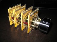
I'll be wiring up the monster in the attached picture when I get some free time to order all the SMD resistors.
Cheers,
Owen
DualTriode:
I've been using the volume control on the M-Audio (it's a USB standalone version, which has an analog control) and with the NTD1, I've been using the "volumite" with the Buffalo DAC to do volume control there. I've never actually measured the performance of volumite, so I might do that at some point. Overall though, it works very well, and you can mount the 5k pot anywhere you want.
As for input impedance, the standard kit will be 10k balanced as built (10k per balanced phase). You could easily change that to 100k or anywhere in between if you'd like, simply by swapping the input R's. Keep in mind that higher input impedance will have higher noise, but it won't be much.
qusp:
I'm glad you found that schematic... it's tucked away on the first page a few posts in.
As for those caps, I'd stick to polymer for the bulk decoupling, and ceramic for anything local. You're not going to beat the performance of a good ceramic when it comes to bypass duties, but if you're after higher values for bulk decoupling, then polymer is best. What you could try is reducing the value of the ceramic caps to the point that you could get a C0G/NP0 dielectric in there, but they can get very expensive very quickly, and I'm not sure there would be a real benefit.
I think I might try one of my amps in a portable setup as well, with just a pair of 9V batteries. I tested performance with 12V rails, and there was no degradation visible, so you're safe running them there. If you do that, you should definitely band limit the 49600 as it draws significantly less current in that mode, and will really prolong battery life. Lower rails will also help in this regard.
icewall:
I'd suggest one of these (the quad version for stereo balanced) if you have the cash:
Prices
Otherwise, there are several other switched attenuators out there for far less money. I think I remember reading about one from Poland that looked very well made, and decently priced.
Unless your source is very low output, I wouldn't bother with anything active. If you're on a tight budget, there are very cheap dual gang 12 step selector switches which would allow you to do dual mono balanced attenuators (one knob per channel). Take a look on Digikey or Mouser.
I'll be wiring up the monster in the attached picture when I get some free time to order all the SMD resistors.
Cheers,
Owen
Attachments
yeah i was going to stack the polymer (and possibly np0) directly on top of the ceramic, not replacing it, but adding backup, then i could possibly go to smaller np0 as you say, i have some 100nf np0 already as i bought in bulk for my dac for a reasonable saving. the polymer caps however are not rated high enough so the question was moot.
i also got some lme49610 which i dont expect to make any difference, but given they are only marginally wider bandwidth, i dont see there will be a problem with 200mhz vs 180, noticed you had shorted vee to BW i assume you tried both ways (this has been covered I know). i think if i went portable i would definitely undo that and lift bw, not just for battery life, but being someone who uses portable amps and dacs quite a lot with my headphones on public transport, at least here mobile phones and telecommunication are a problem for interference; i would think if anything is going to make it oscillate the location 'ping' to the tower just before a phone starts ringing is it
i also got some lme49610 which i dont expect to make any difference, but given they are only marginally wider bandwidth, i dont see there will be a problem with 200mhz vs 180, noticed you had shorted vee to BW i assume you tried both ways (this has been covered I know). i think if i went portable i would definitely undo that and lift bw, not just for battery life, but being someone who uses portable amps and dacs quite a lot with my headphones on public transport, at least here mobile phones and telecommunication are a problem for interference; i would think if anything is going to make it oscillate the location 'ping' to the tower just before a phone starts ringing is it
Last edited:
nice pot btw, thats one of the old khozmo units right? or something else of your design? obviously you were looking at using all smd zfoils right? lol
i'll be interested in the measurements of the volumite, i expect them to be very very good, i find it excellent, the smooth action and perfect matching all the way down is awesome
i'll be interested in the measurements of the volumite, i expect them to be very very good, i find it excellent, the smooth action and perfect matching all the way down is awesome
Last edited:
Hello All,
Of volume controls, in the analog domain i use stepped attenuators between two buffers. The thought is that a low output impedance buffer is better suited driving a given amplifier than some random source that you may plug in. if you have a 10K ohm or 200K input impedance that is ok. Keep an eye on the value of the coupling capacitor.
A voltage divider lowers both the noise and signal equally for the preceding stages then adds Johnson noise of its own.
A volume control operating by software / firmware in the DAC chip’s digital domain operates stepwise to reduce the number of volume steps progressively less smooth as the volume is reduced. The noise level remains unchanged. The highest S/N ratio is at maximum volume.
None of the above may make any difference when the headphones are on my head and the music is playing. Worth a try!
DT
All just for fun!
Last edited:
sabre works somewhat differently, as the control operates at 32 bit and audio is 24bit, it is not a linear expression and audio signal dnr does not become effected at all until you have reduced a significant amount. at least thats how i understand it. either way subjectively its been the best and cheapest; a very rare combination
yes steppers and relay based controls are my favorite of the analogue, but i just dont use them anymore, for me it becomes very expensive given the silly amounts i tend to spend on resistors and even then it is flawed imo; especially given the extra money and extra circuits like your buffers you need to add to fix the problems they create
yes steppers and relay based controls are my favorite of the analogue, but i just dont use them anymore, for me it becomes very expensive given the silly amounts i tend to spend on resistors and even then it is flawed imo; especially given the extra money and extra circuits like your buffers you need to add to fix the problems they create
Last edited:
tongue tied, not sure i made sense so its gone
everything has its trade off
Hello qusp,
Makes perfect since to me.
Lots of options to learn and play with. Hook it all up all up and run the Fast Fourier transform and see how they compare.
The first effort with “The Wire” will be with the balanced output E-MU.
The source i use most often is vinyl, my entire assortment of RIAA equalizers is single ended. Now with this “The Wire” and the balanced power amps in use i see a balanced output B1 (thanks Papa) in the future.
DT
All just for fun!
For attenuation, I went ahead and ordered one of these:
High Quality Audio & Industrial Attenuators
It just seemed appropriate to stay on the SMD scheme. I also like the fact it has 48 steps vice the 23 of the goldpoint.
BTW, I will be making my build single ended through out. I might also increase the gain to 2X to make it a bit more universal for my intended sources. We shall see.
yeah i mentioned those, imo they are te best option on the market at the moment when it comes to steppers. did you buy it direct or through pcx? pcx has the option of using zfoil shunt resistors which is cool, though easy enough to do yourself. so as you are se, you just went with a stereo model yes? shunt or series? and heres an interesting question, will you actually recieve the model you ordered? have they sorted their development phase out? i prefer the look of the old model, but this one is still very cool. i would be buying the shunt version and breaking out a few ASMP smd zfoils for the shunt resistors. at least from pcx they tell you what is in stock
jdkJake,
That's exactly the stepped attenuator I was thinking of! They were from Poland, but I couldn't for the life of me remember what the name of the company was.
I think I'll actually be ordering one of those just to have around. They're beautifully made, and as you said, the more steps, the better with stepped attenuators.
I wonder if they would do a ladder type balanced attenuator with the 8-pole version?
Cheers,
Owen
They have two resistors in the signal path.
That's one two many.
Plus doubling the copper track, solder, contacts.
In about 1996 I made one for a friend with just one series Vishay and a bunch of switched shunt resistors; Vishay VSH.
I used a Shallco switch I bought from Michael Percy. IIRC, guaranteed for 25 years, 2mOhms contact resistance, 10 amps. Solid silver alloy, not plated, silver greased.
I eventually found that even a switch that good was not good enough and I just used one single volume level with a Vishay series and shunt in the leads at the amplifier end.
Audio Synthesis used this Shallco switch in their 'Passion' passives.
I do have a volume control now, it's software I presume, in windows or in maybe the the CMedia DSP on the Auzentech PC sound card. It seems to have no degradation in sound quality. I have a 32 bit resampler that can be used as an adjunct to Winamp specially to set the volume, but with the system as it currently is, I can't tell any difference with it on or off.
Last edited:
yeah i mentioned those, imo they are te best option on the market at the moment when it comes to steppers. did you buy it direct or through pcx? pcx has the option of using zfoil shunt resistors which is cool, though easy enough to do yourself. so as you are se, you just went with a stereo model yes? shunt or series? and heres an interesting question, will you actually recieve the model you ordered? have they sorted their development phase out? i prefer the look of the old model, but this one is still very cool. i would be buying the shunt version and breaking out a few ASMP smd zfoils for the shunt resistors. at least from pcx they tell you what is in stock
I bought it direct. Communications with Arek of Khozmo was excellent. He was very prompt answering email and answered all of my questions. I have not received the part yet, but, so far, the experience has been fine. Heck, I haven't received my "Wire" kit yet, so, I guess I will see who is faster; Canadian Post or Poland Post. For the record, Canada had a head start.
")
BTW, I specifically requested the SMD model shown on the web page I linked in my previous post. They still offer the other model, which, is far more configurable in terms of resistor-brand choices:
High Quality Audio & Industrial Attenuators
Again, I went with the SMD version as it felt more appropriate for this amp design. They will custom configure a part to your specifications, you just need to ask. It appears they build to order anyway, so, I cannot see it taking much longer unless any custom/unique parts have to be acquired. I went for the stereo version at 50K. It is a series resistor into a ladder shunt to determine the final attenuation value.
I wonder if they would do a ladder type balanced attenuator with the 8-pole version?
They might. Drop them an email. Arek is pretty easy to deal with and respond quickly (at least he did with me).
They have two resistors in the signal path.
That's one two many.
Plus doubling the copper track, solder, contacts.
Perhaps, but, I still need an attenuator for my intended use, so, this will have to do as a compromise. IMO, I think it is more appropriate than log or shunted linear pot, at least in terms of potential accuracy and channel matching. Since I am going single-ended, I might be able to get away by not populating R2/R5 and R8/R11. The series resistor of the attenuator could act as a surrogate for this position, thereby "eliminating" one of the resistors from the signal path. Too early to tell yet, I will have to play around a bit and see what works best.
Should be a interesting build regardless.
actually i prefer the idea of the smd version anyway, shorter signal paths and all that. plus the asmp zfoils are actually cheaper than the leaded version and melf are easy to find and easy to replace. they really are very cool and if i needed a pot i would be getting one of them. i may look into them for my daox or circlotron, plus they are just so god damn sexy
so opc, does the tab on the buffer need t be soldered to the board? or will silver epoxy, or just contact with the 'heatsink' be enough? because i was thinking of tinning the pad lightly and then heating the tab to try and solder it there. is this how it works in your board? i have always had a small amount of overhang to solder it to.
When I built mine, tinning the pad lightly and heating the tab is exactly how I did it. Here's the technique I used to solder the buffer tab:
1) Apply flux to the PCB and lightly tin the entire pad, leaving a slightly elevated "bump" or "ridge" of solder at the top of the pad. This will be useful later to determine that the solder underneath the buffer has melted when we're soldering the tab. Apply more flux to the pad.
2) Apply flux to the back of the LME49600 buffer, but do not tin it (I didn't, at least). Carefully place the buffer on top of the pad, making sure you give yourself enough room at the bottom of the buffer's 5 pins to apply solder to both the pad and the pin later on. The buffer should be raised off of the PCB slightly (a fraction of a millimeter) near the top of the tab due to the solder "ridge" we made.
3) Using a chisel tip on your iron, set your soldering station to 375°C and overflow the tip with solder. Put pressure on top of the buffer with a pair of tweezers to hold it down. Place the chisel tip flat-face down on the PCB right above the buffer such that the side of the tip is in contact with the top edge of the buffer's tab. Slowly run the side of the tip "up and down" the top edge of the tab to heat it up to the solder's melting point. After ~5 seconds or so the buffer should "drop" oh so very slightly, and it's at this point that we know that the solder underneath the tab has melted. Keep running the iron against the tab for ~1-2 more seconds to make sure all of the solder underneath has melted, then remove the soldering iron. Remove pressure from the top of the buffer once you give enough time for the solder to solidify.
One more tip for builders: I found it much easier to solder the components in the order of resistors, op-amps, then ceramic bypass capacitors. The height of those caps gets in the way of soldering the op-amps precisely, but if you solder them afterward they are generally placed on the outside, giving your iron much more room.
Hope this helps!
yeah technique is fine, have done with other components, nice post though. i agree as with anything smd that doesnt have a stuffing order specifically given for testing is simply smallest to largest components. sometimes i have struck boards that will have a through hole under the pad that needs to be tinned and then soldered from the other side of the board.
Last edited:
- Home
- Amplifiers
- Headphone Systems
- "The Wire" Ultra-High Performance Headphone Amplifier - PCB's