Good to hear you got that working.
What did you do (or do you suggest) to determine if the regulator was broken.
Or did you just swap in another one?
(I am having some power supply problems again - I lost my positive side - (need to keep positive) - I may have messed up my transformer... it is getting hot ~140F. )
Thanks
What did you do (or do you suggest) to determine if the regulator was broken.
Or did you just swap in another one?
(I am having some power supply problems again - I lost my positive side - (need to keep positive) - I may have messed up my transformer... it is getting hot ~140F. )
Thanks
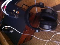
Hi, all. Almost finished my build.
Here it is. Planned for a small/medium footprint desktop amp, paired with a remoted volume control module. CAD/CAM building in our machine shop.
The volume module is bought from a designer in China two years ago. MCU control board (close to the front panel) + realy/resistor network (close to the back plate), 10 relays and (typically) 100 logic sound levels, 3 alternative curves. The pot-like thing is an encoder that gives input to the MCU. The module is programmed to learn any IrDA remote control, so yeah, your smartphone works if it has an IrDA emitter. Very robust and well thought in details. Thank the designer.
R-core transformer ebayed, too. I like it having multiple secondaries feeding different modules in the build. LED integrated switch from radioshack,") . Happen to have a roll of shielded twisted pair power control cable, so used for the mains. Might vialate the grounding rule a bit here.
. Happen to have a roll of shielded twisted pair power control cable, so used for the mains. Might vialate the grounding rule a bit here.
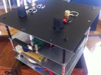
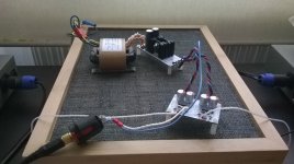
The transformer was pretty close to the circuits due to the small chassis layout, so I milled a slot on the bottom and top plate and tapped a threaded hole, which hold two stacked steel sheet as a isolation plate (plate removed). Not really much audible change in a rush test. Worst case I can paste some mumetal foil, but that is expensive.
The whole job is done on some ebayed aluminum chassis (keyword: 2207S, indicating its dimensions)and took some milling work. The chassis is bit of warped, gave me some troubles in the work. Some misalighnment of holes, breaking drill bits, etc. The seller offered to customize the chassis, at a cost of cource - good for those who have difficulty accessing machine tools. The LED digits were on the control board, and I do not have enough room on the front panel to mount it there. So I built a daughter board and flywired the digits and the Infrared receiver. Congested space there get me layout the wiring in a "feather like" way. They are just constant DC current when not adjusting, so should not be a problem.
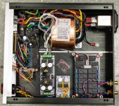
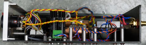
I hanged the amp board and relay boards high in the chassis to wire them from both sides - quite convenient.
Thanks Owen designing it. Thank him and all others helped me.
An externally hosted image should be here but it was not working when we last tested it.
Here it is. Planned for a small/medium footprint desktop amp, paired with a remoted volume control module. CAD/CAM building in our machine shop.
The volume module is bought from a designer in China two years ago. MCU control board (close to the front panel) + realy/resistor network (close to the back plate), 10 relays and (typically) 100 logic sound levels, 3 alternative curves. The pot-like thing is an encoder that gives input to the MCU. The module is programmed to learn any IrDA remote control, so yeah, your smartphone works if it has an IrDA emitter. Very robust and well thought in details. Thank the designer.
R-core transformer ebayed, too. I like it having multiple secondaries feeding different modules in the build. LED integrated switch from radioshack,
. Happen to have a roll of shielded twisted pair power control cable, so used for the mains. Might vialate the grounding rule a bit here.The transformer was pretty close to the circuits due to the small chassis layout, so I milled a slot on the bottom and top plate and tapped a threaded hole, which hold two stacked steel sheet as a isolation plate (plate removed). Not really much audible change in a rush test. Worst case I can paste some mumetal foil, but that is expensive.
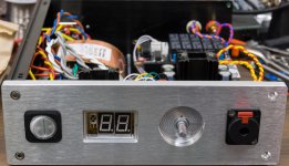
The whole job is done on some ebayed aluminum chassis (keyword: 2207S, indicating its dimensions)and took some milling work. The chassis is bit of warped, gave me some troubles in the work. Some misalighnment of holes, breaking drill bits, etc. The seller offered to customize the chassis, at a cost of cource - good for those who have difficulty accessing machine tools. The LED digits were on the control board, and I do not have enough room on the front panel to mount it there. So I built a daughter board and flywired the digits and the Infrared receiver. Congested space there get me layout the wiring in a "feather like" way. They are just constant DC current when not adjusting, so should not be a problem.
I hanged the amp board and relay boards high in the chassis to wire them from both sides - quite convenient.
Thanks Owen designing it. Thank him and all others helped me.
Last edited:
Hi, all. Almost finished my build.
Here it is. Planned for a small/medium footprint desktop amp, paired with a remoted volume control module. CAD/CAM building in our machine shop.
The volume module is bought from a designer in China two years ago. MCU control board (close to the front panel) + realy/resistor network (close to the back plate), 10 relays and (typically) 100 logic sound levels, 3 alternative curves. The pot-like thing is an encoder that gives input to the MCU. The module is programmed to learn any IrDA remote control, so yeah, your smartphone works if it has an IrDA emitter. Very robust and well thought in details. Thank the designer.
R-core transformer ebayed, too. I like it having multiple secondaries feeding different modules in the build. LED integrated switch from radioshack,
The transformer was pretty close to the circuits due to the small chassis layout, so I milled a slot on the bottom and top plate and tapped a threaded hole, which hold two stacked steel sheet as a isolation plate (plate removed). Not really much audible change in a rush test. Worst case I can paste some mumetal foil, but that is expensive.
The whole job is done on some ebayed aluminum chassis (keyword: 2207S, indicating its dimensions)and took some milling work. The chassis is bit of warped, gave me some troubles in the work. Some misalighnment of holes, breaking drill bits, etc. The seller offered to customize the chassis, at a cost of cource - good for those who have difficulty accessing machine tools. The LED digits were on the control board, and I do not have enough room on the front panel to mount it there. So I built a daughter board and flywired the digits and the Infrared receiver. Congested space there get me layout the wiring in a "feather like" way. They are just constant DC current when not adjusting, so should not be a problem.
I hanged the amp board and relay boards high in the chassis to wire them from both sides - quite convenient.
Thanks Owen designing it. Thank him and all others helped me.
Failed getting a photo link... No idea how to get the static URL of a photo. Link here.
https://www.dropbox.com/s/ne9owol4f5p9adf/_IMG1539.jpg
https://www.dropbox.com/s/qk0frcnq5d80jac/_IMG1540.jpg
https://www.dropbox.com/s/z2f3ml30g1zaw8e/_IMG1541.jpg
Last edited:
Failed getting a photo link... No idea how to get the static URL of a photo. Link here.
https://www.dropbox.com/s/ne9owol4f5p9adf/_IMG1539.jpg
https://www.dropbox.com/s/qk0frcnq5d80jac/_IMG1540.jpg
https://www.dropbox.com/s/z2f3ml30g1zaw8e/_IMG1541.jpg
Very nice! I can only hope mine comes out half as good as that
Just attach your pics.
Just learnt to scroll down
thank you all for your kind words.
Yet to finish the acrylic cover plate and volume knob. Enjoyed it last night and like it very much.
This project gets me wonder the right gain for a headphone amp. True, there are tough to drive headphones, but most dynamic headphones and IEMs give enough sound pressure at a very low voltage.
Note that OSHA/NIOSH suggested value of 8hour average noise exposure is only 85dB (or 90dB, a older regulated threshold), and I consider that as the "health limit". HiFi world favors “suficient redundance", thus why not give our precious ears some redundance?
~0.1Vrms signal would be enough to drive many(most?) popular cans to/beyond 85dB level (taking HD650 as the target here). Ear bleeding level (110dB?) would be of some 1Vrms or so for them, too.
Considering 2Vrms source output, that means the amp should damp the signal most of the time and unity gain is already too loud for many. Owen's argument of low gain amp makes sense to me, after building some higher gain amps and never needed to turn the pot beyond 1/4. Furthermore, under such a small output, I am not sure many high performance amps perform well. Similar thing for speaker amps, too, for their watt rating needed.
Attachments
It's amazing how little gain you really need with most headphones. I'm trying to decide wether to go with 1x or 2x for my SE-SE build. I use 1x gain on my O2 and it's loud enough for me with my 1Vrms source and Grados. I'm just wondering if it would be enough with different headphones since I thinking of getting a pair of HD600s to replace the Hd598s that a family member "borrowed". What do you guys think?
Some very nice looking builds from you guys Really need to finish off my BAL-BAL build, but am waiting on 'The Wire' DAC... hint, hint, nudge, nudge
Gain... as has been pointed out, even 1Vrms will drive a lot a headphones to very loud levels. Base gain on the SE-SE is 1.1, it's output should drive a set of HD600 very well
Really need to finish off my BAL-BAL build, but am waiting on 'The Wire' DAC... hint, hint, nudge, nudge Gain... as has been pointed out, even 1Vrms will drive a lot a headphones to very loud levels. Base gain on the SE-SE is 1.1, it's output should drive a set of HD600 very well
Talema 62052 trans.
Would this be a suitable transformer if I'm planning to use 12v rails for my SE-SE build?
Would this be a suitable transformer if I'm planning to use 12v rails for my SE-SE build?
Talema 62052 trans.
Would this be a suitable transformer if I'm planning to use 12v rails for my SE-SE build?
Link seems to be broken...
Invalid Request
Hopefully that one works. If not it's digikey.com part#1295-1064
Hopefully that one works. If not it's digikey.com part#1295-1064
I think I found the info I was looking for and it looks like that trasformer will be fine. If I want to run 12v rails I would just change r30,55 to 134K and leave r29,52 at 1.24M? Sorry for all the dumb questions I just want make sure I get my parts order correct. Nothing I hate more then being in the middle of a project and I realize I'm missing a single resistor and then I have to spend $5 shipping for a 10cent part 
I think I found the info I was looking for and it looks like that trasformer will be fine. If I want to run 12v rails I would just change r30,55 to 134K and leave r29,52 at 1.24M? Sorry for all the dumb questions I just want make sure I get my parts order correct. Nothing I hate more then being in the middle of a project and I realize I'm missing a single resistor and then I have to spend $5 shipping for a 10cent part
For -12V, the datasheet suggests 1.5M ohms and 162k, but what you have listed (from the BOM I assume) will work as well.
Also, the transformer you have listed should be perfect for 12V rails and powering an SE-SE.
Best of luck with the build!
Regards,
Owen
For -12V, the datasheet suggests 1.5M ohms and 162k, but what you have listed (from the BOM I assume) will work as well.
Also, the transformer you have listed should be perfect for 12V rails and powering an SE-SE.
Best of luck with the build!
Regards,
Owen
Thanks for your help
. I did notice that the data sheet recommended different resistor values then the BOM which is why I figured it was best to ask. I think I'm going to stick with what's on the BOM just to keep things as simple as possible. I'm really looking forward to this build it will be interesting to see how it compares to my O2!I removed the big caps on output side of the PSU. I prefer it this way. For me this is a lot better withe the BAL-BAL. Bass absolutely still there just more precise and defined without any boom. There was something bothering me with the sound but now its relay clean and uncolored.
//
//
Attachments
Last edited:
- Home
- Amplifiers
- Headphone Systems
- "The Wire" Ultra-High Performance Headphone Amplifier - PCB's