Hi Tame,
For the BAL-BAL the gain is set as follows:
Assuming Rf = R21 = R24 = R25 = R28 and Ri = R22 = R23 = R26 = R27
Then the gain (Av) is simply Rf / Ri.
The standard BAL-BAL schematic shows Rf = 1k and Ri = 1k, so the gain is 1k/1k = 1, or in dB, that's 0dB or unity gain.
If you want more gain, you simply increase Rf or reduce Ri. If you increased Rf to 2k, then the gain becomes 2k/1k = 2 or 6dB.
It's also worth noting that Ri sets the input impedance, so using a very low value of resistor here could load the previous stage, especially if it's fed by a potentiometer. This needs to be balanced out with the use of excessively high resistance values for Rf, which will increase noise.
If you're using a 10k pot in front of the BAL-BAL in a BAL-SE configuration, then I would suggest using 10k for Ri and 20k for Rf. If you put your 10k pot in front of this, then you'll lose 6dB thanks to the resistor divider formed by the 10k pot value and the 10k input impedance, but you'll have 6dB gain in the amplifier itself which means a net gain of 0dB for the whole system.
If you're using an active preamp, with a buffer at the output, then just leave the BAL-BAL as configured with 1k resistors for Rf and Ri.
Regards,
Owen
I ended up with that transformer you previously recommended to me -- the super small one from digi-key. Here is a pic of its schematic:
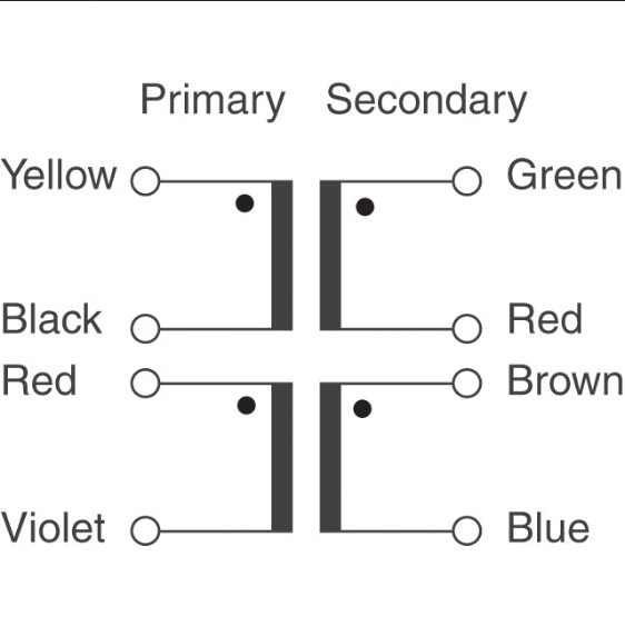
Not sure which one is mains and which one is neutral but if I were a betting man I'd say the yellow is mains and black is neutral. Same with red and violet. If I want to make a center tap and create 15-0-15 wouldn't green and blue be tied together and sent into CT on my supply? And then brown goes into one of the AC holes and red goes into the other?
I'm reading through this thread. So I'm still back in 2012. Post 15555. Just ordered the BAL-BAL. And on my way to find out how to add items not part of the BOM.
Link to that transformer please ? Or partnumber.
Recomended by jdkJake.
I probably order everyting from DigiKey, as the freight is free.
Last edited:
This one maybe ?
62043-P2S02 Acme Electric/Amveco/Actown | TE62043-ND | DigiKey
"Digi-Key has discontinued this item; limited quantity available."
So I have to hurry, or is there a better or a similar one I could purchase ?
Edit:
They suggest this substitute.
http://www.digikey.com/product-detail/en/62043/1295-1068-ND/3881353
So I can use any of them ?
Last edited:
I think 10VA might be a bit too low. That one looks ok - VPT30-830 Triad Magnetics | 237-1326-ND | DigiKey
In Poland we have some nice custom made transformers especially made for audio. They are amazing quality, dead quiet, electrically shielded and epoxy sealed and not so expensive. You may check it.
http://sklep.toroidy.pl/en_US/p/TTSA0030-Transformer-AUDIO-TSA30VA-voltage-to-50V/307
In Poland we have some nice custom made transformers especially made for audio. They are amazing quality, dead quiet, electrically shielded and epoxy sealed and not so expensive. You may check it.
http://sklep.toroidy.pl/en_US/p/TTSA0030-Transformer-AUDIO-TSA30VA-voltage-to-50V/307
Found answer here :
http://www.diyaudio.com/forums/head...headphone-amplifier-pcbs-191.html#post3717484
So now it's only to decide which one to purchase ref my post #2404 above.
I guess I won't do anything wrong if I choose the alternative one.
http://www.diyaudio.com/forums/head...headphone-amplifier-pcbs-191.html#post3717484
So now it's only to decide which one to purchase ref my post #2404 above.
I guess I won't do anything wrong if I choose the alternative one.
Last edited:
R1200CL:
I would probably suggest going a little higher than 10VA, but it's not critical. 10VA will work, by you'll see some voltage sag on the secondary windings prior to the regulators at full power.
I would probably opt for 15 to 25VA instead and pick a secondary voltage that meets your target rail voltage (eg, 15VAC for 16VDC rails, or 12VAC for 10-12VDC rails).
A quick search through Digikey will find you several that fit the bill. As BamboszeK mentioned in his post though, you might be better buying the transformers somewhere other than Digikey as they charge a large premium for anything heavy to offset the shipping cost.
Regards,
Owen
Hi Tame,
Rf and Ri stay the same.
You ground the negative input and feed the signal to the positive input.
All the same guidelines apply as I wrote before, but you only need a single gang pot per channel instead of the dual gang pot you'd have needed for balanced.
Regards,
Owen
Rf and Ri stay the same.
You ground the negative input and feed the signal to the positive input.
All the same guidelines apply as I wrote before, but you only need a single gang pot per channel instead of the dual gang pot you'd have needed for balanced.
Regards,
Owen
Hey @opc,
The AMP circuit is indeed great. I just did not understand the purpose of adding the 10k resistors to GND at the buffer inputs? To reduce offset?
Also, has anyone tried it with an OPA1611/12 instead of LME49990 or in fact just any other opamp than this? What was the performance of it? Did it sound better?
Gents, where can I get PCB's ?
opc's order page is over here. In the first post he has a link to a spreadsheet where you can enter your order.
Please, the project is a little confusing to me.
According to the schematic, you have:
- Circuit for balanced inputs. OK
- Circuit for unbalanced inputs. OK
- Circuit power supply. OK
* The following circuit refers to what exactly? An extra buffer (OPA1632 + 2x LME49600)?
From what I understand through the images posted, people are using using only one of the circuits.
But I noticed that are single voltage gain, it is for each adjust the gain to your liking? I see the positive input is also grounded?
Or that extra buffer the gain is adjusted?
I intend to ride the circuit for unbalanced inputs, but really got confused with the latter circuit and compared to the gain adjustment as well.
Thanks for listening!
OPC
Can I ask one question regarding bypassing the supply for the LME49610? The data sheet suggests:
I note you chose to place a single 10uF ceramic. Can I ask the rationale behind this decision?
Thanks in advance
Steve
Can I ask one question regarding bypassing the supply for the LME49610? The data sheet suggests:
In these and similar situations, place the parallel combination of a solid 5μF to 10μF tantalum capacitor and a ceramic 0.1μF capacitor as close as possible to the device supply pins.
Ceramic capacitor have very lower ESR (typically less than 10mΩ) and low ESL when compared to the same valued tantalum capacitor. The ceramic capacitors, therefore, have superior AC performance for bypassing high frequency noise.
I note you chose to place a single 10uF ceramic. Can I ask the rationale behind this decision?
Thanks in advance
Steve
Hi Steve,
The "multi cap bypass" idea is ages old, and really dates back to a time when capacitors were leaded, and not all that good. Amazingly, this advice tends to stick around in datasheets everywhere even though it's actually bad advice.
When people parallel 3 different caps on a single pin, lots of things happen. They think "Hey, the little 0.1uF ceramic will have low impedance at very high frequencies, the 1uF film cap will have low impedance at mid frequencies and the 100-1000uF cap will have low impedance at very low frequencies".
This sounds great on the surface, but that's not how it actually works in practice. If you put those three caps on a PCB and measure the resulting impedance with a network analyzer, you get a veritable mess. It's not a nice broad low impedance, but rather a much higher impedance and a rather peaky mess.
There's an article that touches on it here:
LM3886 chip amp supply decoupling.
Unfortunately, these are simulations, so they don't necessarily reflect reality which is worse when measured directly.
In the end, a single good quality SMD ceramic part mounted very closely to the pin and grounded to a full ground plane will provide the best possible HF performance, and a larger nearby bulk cap will keep impedance low at low frequencies as long as a large power planes are used. Modern SMD ceramic parts have extremely low ESR/ESL over a very broad frequency range and the upper limits are often bound more by the package leg and PCB layout than the capacitor itself. At audio frequencies (and generally for bypassing circuits whose BW doesn't exceed 3MHz) the value doesn't matter all that much since anything from 0.1uF to 22uF provide very low impedance even at very high frequencies.
Regards,
Owen
- Home
- Amplifiers
- Headphone Systems
- "The Wire" Ultra-High Performance Headphone Amplifier - PCB's