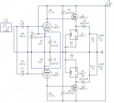
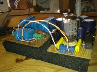
Yesterday evening I built a hybrid headphone amplifier based on a design published over at DIY Audio Projects: NP-100v12: DIY 12AU7 (ECC82) Tube / IRF510 MOSFET Headphone Amplifier.
It's the first headphone amp I've built, and also the first time I've built something with tubes. This may interfere with my perception, but I still think it's a very nice amplifier.
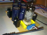
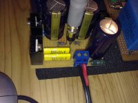
I used what I found in my various junk boxes, hence the odd values. The input caps are Nippon Chemi-Con FNX-HS 1uF 100V foil capacitors from a discarded power supply, in case someone is interested. All other caps are Panasonic FC, the resistors are from the Vishay MRS25 series (copper leads, magnetic endcaps, 1%, 0.6W).
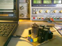
Here's a few numbers I've pulled from the circuit (with no signal present; DMM):
V_supply=12.6V from a benchtop linear PSU (that I rescued from a container)
I_supply=0.38A (reading from display)
Left channel:
V_gate=10.90V
V_source=7.06V
V_cathode=0.063V
Right channel:
V_gate=11.01V
V_source=7.24V
V_cathode=0.059V
The tube's heaters are wires in series, and the center tap measures 6.30V to ground.
Quite interestingly the circuit simulation spit out values surprisingly close to reality:
I_supply=0.32A
V_g=11.05V
V_s=7.31V
V_c=0.059V
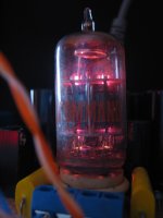
At the moment the tube is a Valvo ECC82 that measured the following (Eico 666 with 12AU7 settings from 667 master settings chart): 119%/106%
I'm guessing this imbalance is at least partially responsible for the different L/R voltage levels.
I'm listening through my Sony MDR-EX71SL (Mr. Linkwitz seems to like them: Reference earphones, almost at the bottom), the source is a Lenovo S10e with FLAC and it's ALC269 audio chip (which Ilike). The amp sounds a bit distorted, but not unpleasant. The bass is incredible, the sound as a whole very involving.
The simulation suggests the distortion is mainly 2nd harmonic (surprise...), with the 2nd being 40dB down, and the 3rd 70db down.
Nevertheless a fun, cheap and quick project. Gonna roll me a tube now...
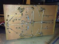
Attached you'll find my actual schematic and some pics.
It's the first headphone amp I've built, and also the first time I've built something with tubes. This may interfere with my perception, but I still think it's a very nice amplifier.
I used what I found in my various junk boxes, hence the odd values. The input caps are Nippon Chemi-Con FNX-HS 1uF 100V foil capacitors from a discarded power supply, in case someone is interested. All other caps are Panasonic FC, the resistors are from the Vishay MRS25 series (copper leads, magnetic endcaps, 1%, 0.6W).
Here's a few numbers I've pulled from the circuit (with no signal present; DMM):
V_supply=12.6V from a benchtop linear PSU (that I rescued from a container)
I_supply=0.38A (reading from display)
Left channel:
V_gate=10.90V
V_source=7.06V
V_cathode=0.063V
Right channel:
V_gate=11.01V
V_source=7.24V
V_cathode=0.059V
The tube's heaters are wires in series, and the center tap measures 6.30V to ground.
Quite interestingly the circuit simulation spit out values surprisingly close to reality:
I_supply=0.32A
V_g=11.05V
V_s=7.31V
V_c=0.059V
At the moment the tube is a Valvo ECC82 that measured the following (Eico 666 with 12AU7 settings from 667 master settings chart): 119%/106%
I'm guessing this imbalance is at least partially responsible for the different L/R voltage levels.
I'm listening through my Sony MDR-EX71SL (Mr. Linkwitz seems to like them: Reference earphones, almost at the bottom), the source is a Lenovo S10e with FLAC and it's ALC269 audio chip (which Ilike). The amp sounds a bit distorted, but not unpleasant. The bass is incredible, the sound as a whole very involving.
The simulation suggests the distortion is mainly 2nd harmonic (surprise...), with the 2nd being 40dB down, and the 3rd 70db down.
Nevertheless a fun, cheap and quick project. Gonna roll me a tube now...
Attached you'll find my actual schematic and some pics.
Attachments
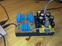
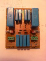
I went ahead and built me a high-Z version of the modified Linkwitz crossfeed filter (article here: HeadWize - Project: An Acoustic Simulator for Headphone Amplifiers by Chu Moy), something I have wanted to do for a long time now. And I'm glad I did, because turned out quite nicely and it's really sweet.
At first it doesn't do much - I even used the "Chromatic Scale" track from Stereophile's Test CD3 to verify that it actually does do something audible, which it does - but after some time the brain seems to appreciate the crossfeed and eases up. Bliss.
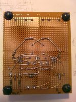
Again i used parts I had laying around. The Wima FKP1 seem to work really well, maybe I'll use them more often in future projects. Wiring the 16 resistors and 10 capacitors was quite a task (I blame the drinking), but at around 3am the circuit was ready and, quite surprisingly, worked.
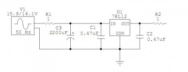
After some sleep I was being annoyed by having to use the benchtop PSU, and not wanting to mess with mains voltage this morning, I dug out an old wall wart powersupply and noticed something funny. The thing is so old it seemingly is a linear supply and has a big transformer inside. It put out almost 20V (unloaded) of what looked quite like DC, even though it was rated for 12V@1.2A. Under load it still exceeded 16V but now had dozens of mV sawtoothy ripple on it.
Copying from the Pearl Two PSU (http://www.passdiy.com/pdf/PEARL 2.pdf) I added a 1R WW resistor, a 2200uF cap, a 7812 regulator bypassed with a 0.47uF foil cap each at in/output and fed the latter via another 1R WW resistor to the circuit.
Works like a charm, and passing ~0.5A the regulator settles at ~50°C. It also (still) sounds excellent.
Very nice project all in all, but the next project will have to be at a higher voltage...
At first it doesn't do much - I even used the "Chromatic Scale" track from Stereophile's Test CD3 to verify that it actually does do something audible, which it does - but after some time the brain seems to appreciate the crossfeed and eases up. Bliss.
Again i used parts I had laying around. The Wima FKP1 seem to work really well, maybe I'll use them more often in future projects. Wiring the 16 resistors and 10 capacitors was quite a task (I blame the drinking), but at around 3am the circuit was ready and, quite surprisingly, worked.
After some sleep I was being annoyed by having to use the benchtop PSU, and not wanting to mess with mains voltage this morning, I dug out an old wall wart powersupply and noticed something funny. The thing is so old it seemingly is a linear supply and has a big transformer inside. It put out almost 20V (unloaded) of what looked quite like DC, even though it was rated for 12V@1.2A. Under load it still exceeded 16V but now had dozens of mV sawtoothy ripple on it.
Copying from the Pearl Two PSU (http://www.passdiy.com/pdf/PEARL 2.pdf) I added a 1R WW resistor, a 2200uF cap, a 7812 regulator bypassed with a 0.47uF foil cap each at in/output and fed the latter via another 1R WW resistor to the circuit.
Works like a charm, and passing ~0.5A the regulator settles at ~50°C. It also (still) sounds excellent.
Very nice project all in all, but the next project will have to be at a higher voltage...
Attachments
is your amp bright sounding?
Bright sounding...hmmm...not that I would have especially noticed. It's rather warm, and very pleasant to listen to for hours.
Why are you asking, if I may ask?
- Status
- This old topic is closed. If you want to reopen this topic, contact a moderator using the "Report Post" button.
- Home
- Amplifiers
- Headphone Systems
- Hybrid headphone amp with 12AU7/ECC82 IRF510 and LM317