Using MOS devices in a Tringlotron topology brings a number of benefits.
The Tringlinator shows a 250mW example.
It is a two-stage design, using no negative feedback.
Yet, thanks to the oustanding error-correction properties of the Tringlo (TRIplet of N-device Grouped in Line) topology, the THD can be as low as 0.001%. (Note that this is a real error-correction scheme, not some NFB in disguise).
The damping factor is in excess of 10,000.
M1 and M2 have to closely match and must be tightly thermally coupled.
The input section provides the voltage amplification and is a variation on the Xquad theme.
Attachments
Last edited:
I've not had time to study the topology yet, however I see that Tringlotron gets a mention on TubeCad.com this month: Tringlotron
Good luck with it.
Good luck with it.
Just before reading this thread, I found this one yesterday (it's in french) :
Applications du Tringlotron à des amplificateurs de classe Audiophile - Forum Projets électroniques
Applications du Tringlotron à des amplificateurs de classe Audiophile - Forum Projets électroniques
after a quick look I would call it "error compensation/cancelation" - for me "error correction" involves a 'measurement" of the error and then involves feedback or Black's output error feedforward
this circuit relies on device matching for the similar Vgs errors to cancel out
this circuit relies on device matching for the similar Vgs errors to cancel out
Compensation, correction, cancellation.... it is debatable.after a quick look I would call it "error compensation/cancelation" - for me "error correction" involves a 'measurement" of the error and then involves feedback or Black's output error feedforward
this circuit relies on device matching for the similar Vgs errors to cancel out
"Error cancellation" is probably the most accurate.
But one thing is unquestionable: there is no NFB involved.
Elvee this looks very interesting. I have a question regarding the bias of M2: the rsisitors R5 and R6 seem to only provide bias for M2, so whay are they relatively low values (k Ohm not M Ohm)? Also, I do not understand why R13 and C2 are across R6... what do they do?
(Thank you)
(Thank you)
But one thing is unquestionable: there is no NFB involved.
except for the local feedback around every transistor in the cirucit
I like making the "no feedback" crowd have to admit they're splitting hairs by distinguishing between "local" and "global" feedback
then mayabe some will ask how come one type of negative feedback is always "good" and the other "bad" - or if its true at all
Fascinating link.Just before reading this thread, I found this one yesterday (it's in french) :
Applications du Tringlotron à des amplificateurs de classe Audiophile - Forum Projets électroniques
I quote (and translate) the original post conclusion:
The TRiNGLotron (TRIplet of NPNs Grouped in Line) is a topology linked to the Biglotron.
Let us remind you that the founding principle of the Biglotron, a creation of Pr. Jérémie Ménerlache, is to serve absolutely no purpose. This foundation allows the Biglotron to be used for virtually anything, conferring it an amazing potential and justifying its status as secret weapon.
The Tringlotron, invented by Ludwig Von Bürnmoll is based on the same principle as its famous ancestor, but is less pretentious. It is not very useful and is thus susceptible to be used for many things.
This is already not too bad by itself, as we will see later on.
The whole thing was posted on the first of April...
Last edited:
Fascinating link.
The whole thing was posted on the first of April...
Then someone tell this guy at ElectronicDesign.com, who posted on April 7th !!! :
http://electronicdesign.com/article/ideas-for-design/novel_buffer_topology_cancels_nonlinearities.aspx
Elvee this looks very interesting. I have a question regarding the bias of M2: the rsisitors R5 and R6 seem to only provide bias for M2, so whay are they relatively low values (k Ohm not M Ohm)? Also, I do not understand why R13 and C2 are across R6... what do they do?
(Thank you)
The bias provided by R5 and R6 is fixed; there is no signal superimposed there, and the node is decoupled to the ground by C2.
R13 is a gate stopper and has an unusually low value because even with ten's of ohms, the Cgd of M2 is sufficient to add some ppm's distortion.
except for the local feedback around every transistor in the cirucit
I like making the "no feedback" crowd have to admit they're splitting hairs by distinguishing between "local" and "global" feedback
then mayabe some will ask how come one type of negative feedback is always "good" and the other "bad" - or if its true at all
Depends where you draw the line: if you consider a common collector stage has 100% feedback, then there is indeed feedback everywhere.
But from that perspective, how would you create a no-feedback unity-gain follower?
BTW, I personally have nothing against NFB, and this is more an exercise in style than anything else.
Fascinating link.
I quote (and translate) the original post conclusion:
The whole thing was posted on the first of April...
Seeing is believing:
Attachments
Last edited:
@Elvee: the idea might indeed works... but the design posted on that french website is a joke played on "audiofools". Another mod of that French forum points to it on p.1 and the original poster admits it on p2.
The design goals of that amplifier:
- being of unrequired complexity
- inconvenient use
- wasteful
- based on a "theme" such as "no NFB"
The design goals of that amplifier:
- being of unrequired complexity
- inconvenient use
- wasteful
- based on a "theme" such as "no NFB"
................................................@Elvee: the idea might indeed works... but the design posted on that french website is a joke played on "audiofools". Another mod of that French forum points to it on p.1 and the original poster admits it on p2.

The thing has more layers than you suspect: beware of reality, it can be much more deceptive than any illusion.
You should know better, you are a native of the cradle of surrealism.
I don't contest how effective this topology is, at least in sims where matching is perfect.
But seriously, whatever its qualities, I wouldn't want to deal with a topology:
- highly dependent on transistors matching,
- with a negative input impedance to take care of,
- with possibly negative output impedance (depending on matching),
- highly susceptible to oscillations,
- with an awful way to connect the load.
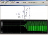
For a little bit of simulation fun, let's add 1nF in parallel with the load.
PS: un doute me prend soudain... seriez-vous Tropique ?
But seriously, whatever its qualities, I wouldn't want to deal with a topology:
- highly dependent on transistors matching,
- with a negative input impedance to take care of,
- with possibly negative output impedance (depending on matching),
- highly susceptible to oscillations,
- with an awful way to connect the load.
For a little bit of simulation fun, let's add 1nF in parallel with the load.
PS: un doute me prend soudain... seriez-vous Tropique ?
But seriously, whatever its qualities, I wouldn't want to deal with a topology:
- with a negative input impedance to take care of,
- with possibly negative output impedance (depending on matching),
How must a source be designed to feed an input that has 'negative impedance'?
How is negative output impedance a problem?
Also, if there are references available so that I may study negative input / output impedance, please advise?
(Thank you)
Hi,
Read the linked article very carefully, especially the "figure a". Pay attention to the proposed current flow.
I think I also read this in "Electronic Design" or some other related magazine I get. It's interesting that this same article appears in more than one magazine in the *exact* same format. Anyway, when I read the first article, I dismissed it very quickly.
Another "sounds too good to be true" things. Anyone try to build it? That would be interesting.
-Chris
I think I also read this in "Electronic Design" or some other related magazine I get.
http://electronicdesign.com/article...l_buffer_topology_cancels_nonlinearities.aspx
: )
Hi Jen,
Yup, that's the one. I get mine in paper. That's because I'm an old fart, plus whenever I get close to a 'puter, there are other pressing things that need tending to.
I don't know about the rest of you, but I have trouble retaining what I read off a computer screen. I greatly prefer paper and even go so far as to print off the interesting articles so I can read later on.
Thank you for looking that up Jen. I suspect it was pretty easily done (I hope).
-Chris
Anyway, when I read the first article, I dismissed it very quickly.
Too quickly, perhaps?
I did build a number of versions; and it is interesting indeed.Another "sounds too good to be true" things. Anyone try to build it? That would be interesting.
Measured performances are far from the sim results, but they are exceptional nevertheless.
I did no serious attempts to match the devices, and anyway, as soon as the prototype was powered, the distortion began to climb due to differences in dissipation in the devices.
A monolithic pair would settle this issue.
The real circuit is a bit temperamental, but much less than in the sim.
In the sim, if you model the parasitic capacitance of the wiring with a capacitor, it will be a "perfect" capacitor, whereas in real life, the wires form a transmission line with 100 or 200 ohm characteristic impedance, which makes a lot of difference.
This doesnt mean you're allowed sloppy standards, but it is not that critical.
In the Tringlinator, most of these issues have been adressed internally, and it will be stable when made and used normally.
Damned! Je suis fait comme un rat!PS: un doute me prend soudain... seriez-vous Tropique ?
It has to be of a much lower absolute magnitude, so that when they are paralleled, the positive part is overwhelmingly dominant.How must a source be designed to feed an input that has 'negative impedance'?
With MOS transistors, this is not too difficult thanks to their large impedance.
Only at high frequencies do parasitic capacitances begin to pose problems.
This issue is adressed with a small parallel capacitor.
With bipolars, the issue is much thornier.
Here is an (extreme) example of what happens when the source impedance is uncontrolled:
Attachments
Hi Elvee,
-Chris
No, I really don't think so. Have you read the article carefully? There must be a reason why current would flow from one point to another. We know it's to equalize the charges, but I don't see that in the diagram.Too quickly, perhaps?
-Chris
Last edited:
- Status
- This old topic is closed. If you want to reopen this topic, contact a moderator using the "Report Post" button.
- Home
- Amplifiers
- Headphone Systems
- The Tringlinator: a MOS-based Tringlotron amplifier