Here's a headphone amp I've been playing around with using a THAT1646 line driver in an unusual configuration to provide bias. It's fully DC-coupled and has low output offset. It's a rather long thread - I've linked in to where the schematic (as a headphone amp) develops. RMAA and FFT tests follow in later posts. People who've built it like the sound. I've posted it over at HeadWize but we can't update there right now and I thought you guys might like to have a peek at it.
Pro Audio Design Forum • View topic - Using the THAT1646 As A Transistor Pre-Driver/Headphone Amp
Wayne
Pro Audio Design Forum • View topic - Using the THAT1646 As A Transistor Pre-Driver/Headphone Amp
Wayne
Wayne, that looks like a cool little project.
I like the fact that the output runs open loop.
Experience suggests that 30 - 60 mW is more than enough for most people with modern high-efficiency headphones, so your design seems spot-on.
Thanks Jen-B. The open loop output throws a lot of people with FB internal to the 1646. I tried a closed loop approach with overall FB during design (to reduce idle current to A-B) and just couldn't get as good of THD performance.
It's unity gain so for some 'phones like the old high impedance AKG-240s it might need some upfront gain but I haven't seen the need for it with modern 'phones. The drive power is indeed adequate for the MDR-7506's I use. The SR is about 8V/us which is plenty for the 1-2V P-P drive.
It's a power hog though - my application was for mastering and non-portable. I've had a few people ask about batteries and I kinda shook my head.
What really surprised me about was the DC performance. I haven't had to match OP devices and the worst offset I've seen is 6-7 mV. So it doesn't require FB or a servo which keeps it simple.
Can a DRV134 be used instead?
theAnonymous1. I really don't know about using the DRV134. I've never tried it. The THAT1646 uses OutSmarts and I tricked it into driving the outputs in "common mode" by using the sense inputs (pins 2 and 7) for signal input and the "normally-used" differential input, pin 4, for complimentary DC Vbe bias.
The DRV134 and SSM2142 use a cross-coupled approach (versus OutSmarts) to line driving. I don't know if driving the sense lines with input produces a "common mode" output. I suspect that they will, but I never tried them. It's easy enough to find out though. I have a DRV I can drop onto the PC board.
I've done comparisons between the DRV134 and THAT1646 as line drivers driving several hundred feet of cable and the FFT performance of both are nearly identical and only second and third visible. They're both very good parts.
I have a DRV I can drop onto the PC board.
I would really appreciate that.
I'm interested in building this, but I hate buying new parts. I have plenty of DRV134.
I tested a DRV134.
It looks like the DRV134 will allow "common mode drive" using its Sense pins as inputs the same way a THAT1646 will.
What is different however, in this unique configuration, is that the differential gain of the DRV134 appears to be twice what the THAT1646 is. This creates bias issues. It does however pass signal and appears to work with an idle current that is far too high.
The Vbe multiplier which drives the THAT 1646 differential input is "mirrored" on the outputs, pins 1 and 8. Other than a few mV of internal 1646 offset the outputs are copies of the Vbe multiplier. One is +Vbe the other an inverted -Vbe. Both Vbe copies are pinned relative to ground in the absence of signal. Since the Vbe multiplier is a third transistor sitting on the heatsink (also a BD139) the thermal tracking is quite good and the offsets low and relatively drift-free.
With the DRV134 having a diff gain that appears to be twice what the 1646's is, the idle current is significantly higher. The Vbe multiplier's output needs to be scaled by approximately 1/2 for it to have adjustment range for idle currents in the 60-80 mA range.
I need to look at why the DRV's (and SSM2142's) differential gain goes from two to four when it's used this way. It's likely a trait of the CCOS topology. A good reference for CCOS outputs is here:
www.proaudiodesignforum.com/Images/pdf/Thomas_Hay_MCI_AES.pdf#page=31 (Figure 24.)
My hunch is that the Vbe multiplier needs to be divided by two before being fed into differential Vin. SInce the tempco of the Vbe multiplier would be scaled and then multiplied again it should track OK. That would require a hack. So I guess the answer to whether a DRV134 can be used is maybe.
Last edited:
I've toyed with this circuit in a simulator using DRV134 model and here is what I came up with:
- Leave everything unchanged. This gives Iq in the 200 mA region. This means 3,5W on every transistor with +-15V supplies. No big deal, I'll just use a bigger heatsink, 14W isn't something to be scared of.
- Use darlingtons istead. Solves current problems but I'm not aware of other possible issues.
- Use a Schottky diode as a reference, according to my simulation, this results in 90 mA'ish currents. Not sure about thermal tracking.
My hunch is that the Vbe multiplier needs to be divided by two before being fed into differential Vin. Since the tempco of the Vbe multiplier would be scaled and then multiplied again it should track OK. That would require a hack. So I guess the answer to whether a DRV134 can be used is maybe.
I finally had a chance to try this circuit using a DRV134 and it only requires the addition of two 470R resistors to scale the Vbe multiplier output by 1/2.
The DRV134 in the "common mode drive" configuration has a differential gain of 4, the THAT1646 has a differential gain of 2.
This causes the DRV134 to have twice the delta Vbe at each output compared to the THAT1646.
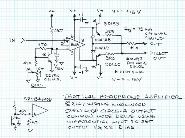
THAT1646 Class-A headphone amp.
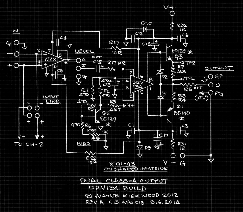
To use the above circuit with a DRV134 (or SSM2142), add a 470R between the collector of the BD139 Vbe multiplier and the 1/25 uF at pin 4. Also add a 470R from pin 4 to ground.
Last edited:
An interesting little circuit. Have you ever tested capacitive driving stability with no "build-out resistor"? (Output series resistors are thoroughly "out", you know. Even a number of "big" cans appreciate <10 ohms, and several multi-driver BA IEMs even want an order of magnitude less.) Since the whole affair is running open loop, that probably won't be too much of an issue, but anyway.
If you've got some sensitive BA IEMs floating around (like Shures, UEs or Westones), you can listen for audible noise, too. If these show a pitch black background with the input shorted, so will everything else.
If you've got some sensitive BA IEMs floating around (like Shures, UEs or Westones), you can listen for audible noise, too. If these show a pitch black background with the input shorted, so will everything else.
Thanks sgrossklass.
Yes, it can be used without the build-out which is there primarily for added short-circuit protection. I've listened to it both ways.
Without the build-out I've driven capacitors >>100 nF. Even with a ridiculous 1 uF I've not seen any sign of instability though as you might expect with 1 uF there is significant triangulation of squarewaves.
This circuit is also being used a cable driver and in that application it's driven over 1000 feet of STP.
WRT to build-outs I can't speak for what's best driving 'phones. I'm sure it depends a lot on the phones.
For balanced cable-driving I've found that build-outs should be optimized. That discussion begins here:
Pro Audio Design Forum • View topic - Balanced Outputs
And some comparative measurements of the SSM2142, DRV134 and THAT1646 both with and without added build-out:
Pro Audio Design Forum • View topic - Balanced Outputs
To give you an idea, here's an impedance plot for UE triple.fi 10s (if that isn't a rollercoaster ride I don't know what is - they are among the most critical ones around), and here's some of the variation you can find among "big" cans:WRT to build-outs I can't speak for what's best driving 'phones. I'm sure it depends a lot on the phones.
An externally hosted image should be here but it was not working when we last tested it.
Headphone cables typically run in the low single-digit nF range.
How did you pick up the signal? If you're measuring single-ended, the full conductor-to-shield capacitance figures in, which would approximately cancel when balanced. And in STP that's pretty big when compared to conductor-conductor capacitance.For balanced cable-driving I've found that build-outs should be optimized. That discussion begins here:
Pro Audio Design Forum • View topic - Balanced Outputs
Additional output resistance essentially counteracts two factors that can cause overshoot and ringing:
1. Amplifier output impedance becoming inductive towards higher frequencies
2. Output stage being slowed down by capacitive loading, which adversely affects 1.
Obviously choosing too high an R eventually restricts bandwidth too much.
Thankfully all of these effects are not terribly relevant at audio frequencies, at least with the kind of cable lengths you'll find at home or in normal-sized studios.
Thanks for the headphone impedance plots. My tests using Sony MDR7506's sounded about the same both with and without build-out. Without seemed a tad tighter in the low end but not much. I chose the added build-out to minimize Isc. You can have it either way.
The cable driving tests were recovered differentially by a THAT1246 or a cross-coupled pair of THAT1286 in some tests. That info is buried in a really long thread.
Burdick (Benchmark) in his clean audio installation guide chose 30 Ohms/leg build-out (for cables) noting that it was not maximally-flat. He had the requirement to transmit HS timecode through his DAs over very long distances and for that reason tolerated the slight peaking. The 40-50 Ohm range (per leg) appears to be maximally-flat. What was interesting to me is that for a given recovered level the peak current requirements and IM of the line driver are significantly lower with a slightly higher build-out. Obviusly there can be too much of a good thing.
I do realize that most people aren't driving 1000' of STP.
The test with it's peak 6V us slew rate may not be real-world either.
Last edited:
I updated the schematic to show the build-out resistor as optional to avoid any confusion that might cause as well as add the mod to use the DRV134.
It's been awhile since I ran capacitive load tests and wanted to confirm that without any build-out it's stable at loads >>100 nF. It is.
A also ran some tests both with and without a 27R build-out driving driving MDR-7506's phones at 100 Hz and the THD is a good 20-30dB lower without the build-out.
For those that have strong feelings against using build-outs to drive phones there's no reason that you have to with this simple circuit other than the additional short-circuit protection it provides.
BTW, I'm still not convinced that this measurement means a whole lot. These 20..30 dB are probably corresponding to the reduction in output impedance, so back-EMF will have proportionally less of an influence. One would have to measure actual acoustic distortion for a meaningful result.A also ran some tests both with and without a 27R build-out driving driving MDR-7506's phones at 100 Hz and the THD is a good 20-30dB lower without the build-out.
When short-circuit protection is desired, I'd normally suggest some extra collector series resistance for the driver transistors... but I don't think an EF output running open loop has enough PSRR to avoid a negative effect on distortion, plus voltage swing is reduced somewhat.
BTW, I'm still not convinced that this measurement means a whole lot. These 20..30 dB are probably corresponding to the reduction in output impedance, so back-EMF will have proportionally less of an influence. One would have to measure actual acoustic distortion for a meaningful result.
I agree. I ran tests similar to what John Siau at Benchmark has done recently.
See: Do Specifications Lie? Do Our Ears Lie? Where does the Truth Lie? An Examination of Headphone Amplifier Performance Specifications | Benchmark Interaction
And: The "0-Ohm" Headphone Amplifier: The Sonic Advantages of Low-Impedance Headphone Amplifiers | Benchmark Interaction
What I did find to be more significant was the reduction in cross-talk:
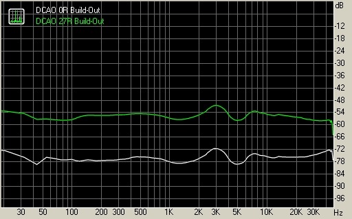
There appears to be significant due to inter-conductor induction.
And an improvement in frequency response flatness:
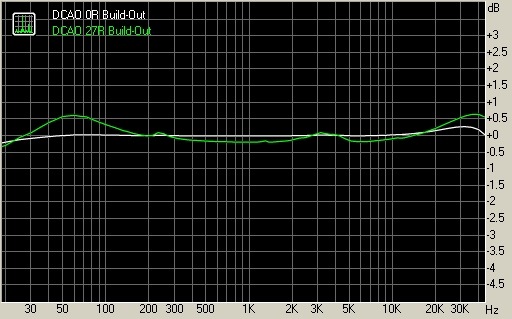
I really want to thank you for pointing out your findings WRT build-outs in your OP.
With regard to my earlier post on the subject of reduced crosstalk.
Lowering the build-out makes it look really good at the connector.
I didn't see that from the beginning.
At the transducer end there's no improvement in crosstalk.
Both ricardo from the Pro Audio Design Forum and John S. set me straight on that.
Regardless one can have it either way: Build-out or none.
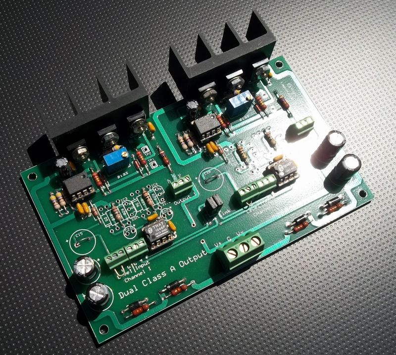
I had some prototype boards made and thought I'd share the pic.
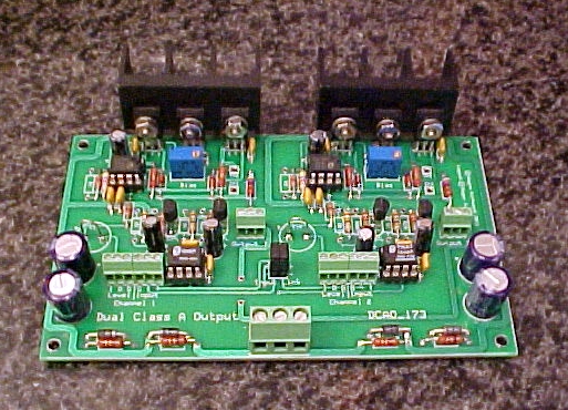
This board is configured so that I can use it as a stereo headphone amp, dual single-ended line driver, balanced line driver with cross-coupled inputs, a studio "re-balancer," and dual output distribution amp.
It is also a very capable transformer driver.
I'm primarily going to use mine as an HPA and a second set of two to provide balanced sound card outputs for test instrumentation.
The outputs are internally ballasted and can also be paralleled to double drive current.
Those jumper links to cross-couple or parallel the inputs prove to be very handy.
I estimate the output impedance (it's open loop) to be <2 Ohms. It can be run with or without build-out resistors into large capacitive loads. 30 Ohm loads can be driven to the 100 mW range with decent performance.
The inputs are balanced using either a THAT1240, 1243 or 1246. There's a Phoenix block for level controls for HPA use. There is no voltage gain but I've found that with the low-impedance phones I'm using it isn't an issue. Having precise unity gain was more important for its' line driver role.
I've run it on supplies as high as +/-18V or as low as +/-9V. Things head south around +/- 6V. I also included a soft clipping circuit which tracks the rail voltage.
As expected for class-A, the current drain is huge. I use 85 mA Iq/channel typically so the totals run about 200-225 mA.
I'll post some RMAA but I'm not sure how accurate they'll be since the sound card masks most of what's going on. I need to setup a null test which is how I originally tested it.
I did some FFTs:
Iq was set to 85 mA per channel.
30 Ohm load at 100 mW. Rbuildout = 0R.
Green is output, Red generator monitor.
The driver adds ~ 0.0017% THD.

Dual Class-A Headphone Amplifier with 30 Ohm load at 100 mW.
600 Ohm load, single-ended, +20 dBu. Rbuildout 0R.
Green is output, Red generator monitor.
Note that the output THD is essentially identical to the generator.
To fully see what the THD is a null test is required.
The driver subtracts ~ 0.0002% THD.
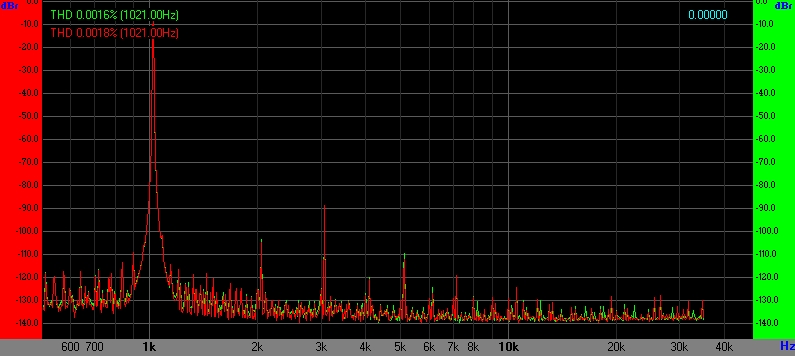
Dual Class-A Line Driver with 600 Ohm load at +20 dBu.
Iq was set to 85 mA per channel.
30 Ohm load at 100 mW. Rbuildout = 0R.
Green is output, Red generator monitor.
The driver adds ~ 0.0017% THD.
Dual Class-A Headphone Amplifier with 30 Ohm load at 100 mW.
600 Ohm load, single-ended, +20 dBu. Rbuildout 0R.
Green is output, Red generator monitor.
Note that the output THD is essentially identical to the generator.
To fully see what the THD is a null test is required.
The driver subtracts ~ 0.0002% THD.
Dual Class-A Line Driver with 600 Ohm load at +20 dBu.
Update showing the DRV134 build and the schematic:
These are a few applications for this high current output in addition to driving headphones:
1) A stereo headphone amp.
2) Dual single-ended class-A line output.
3) Fully-balanced line output with cross-coupled differential input.
4) A high-current line "re-balancer."
5) Dual single-ended or differential transformer driver.
6) Dual output distribution amp.
7) Parallel operation (without external ballast resistors) for double output current.
8) Passive EQ network driver.
9) Control Room Monitor driver.
Last edited:
- Home
- Amplifiers
- Headphone Systems
- Simple Class A Headphone Amp Using THAT1646