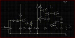
Presented here is a small Class A single ended output headphone amp, unusual because it uses germanium devices.
Why germanium ? Well I have few of these wonderful old devices, and a heaphone amp seemed an ideal little project. There's another reason too... I am working on a new amp (eventually) and headphones are a great way of evaluating circuitry... so I wanted something good.
To anyone not used to seeing and working with germanium, well it probably looks a bit "all upside down" using a positive earth.
Let me say first off that this isn't by any means a "finished" design... it's still a work in progress.
It's 15 years or more since I did any serious headphone listening and my old Sony MDRV-7's were used in the design of this. I must look into more modern replacements.
The low supply voltage probably stands out, 6.8 volts... is it enough for decent output ? Well it appears so for me, and it drives the Sony's to way higher than what would be considered "safe" levels, although the efficiency of these old cans is high I think, compared to some. The supply can always be altered though, and in actual fact isn't the only limiting factor here. That comes from the constant current source Q4 and 5. The 3.3 ohm gives around 50ma in the outputs and at 6.8 volts they run at a reasonable temperature. This is germanium after all. Even swapping this resistor out to 43 ohms still allows decent levels before soft asymetrical clipping occurs.
One thing this design is if nothing else is tweakable... so non of these issues are a major stumbling block. As I say, it's not a final design yet.
The ACY21 is used as a buffer to provide a known input impedance, and to enable the volume control to be unaffected by the signal source... probably an unnecessary extra stage you might think, however listening tests reveal no problems including it... it may even help "soften" the presentation... in the nicest possible way of course. I tried direct onto the volume control, and then with the ACY21 and "think" the extra stage possibly adds a little indefinable something. Q2 and Q6 form a classic two stage amplifier. The supply (no decoupling shown) comes from a 7906 regulator with a 1n4148 lifting the ground leg to provide around 6.8 volts.
So how does it all sound... well I think it's pretty good, but then I would say that wouldn't I. It's certainly more "engaging" to listen to than a normal opamp offering... in fact it's pretty stunning. There is a razor sharp clarity, yet with absolutely no hint of harshness or stridency. I suspect the "not so low" output impedance is actually a match made in heaven for the phones, and playing around with the output impedance is something I want to look further into. The inherently slow (are they slow ? in absolute terms maybe) nature of germanium means that the amp has a natural and well defined HF limit. The 150 pf cap isn't strictly required... it satisfied the more objective aspects of the design ie squarewave testing, which made me feel better which in turn makes the amp sound better 🙂
So that's the design as it stands V1.0
No CD's were harmed in the development of this project. Material used included amongst many others,
Mozart-- Oboe Quartet in F major. Sony 88697285852
Nigel Kennedy-- Polish Spirit. EMI 094637993422
Elton John-- The Superior Sound of. DJM 8100622
Attachments

So has that frightened you all off 🙂 Using germanium. Well put your preconceptions aside... it is a real treat to listen too.
First minor changes from above circuit are,
1. Addition of a 0.1uf cap from the base of Q4 to ground.
2. The 22 ohm output resistor is now 10 ohm.
3. Q1 and Q2 are now 2SD457A
4. Q3 is now a 2SB324
Some actual performance results and thoughts etc.
How much drive is needed... well with music on the Sony cans around 0.8 volts peak/peak (transients) is more than enough for me. Average is around 0.2 to 0.4 volts.
How much output can it deliver... around 4.5 volts peak/peak using the Sonys as a load before clipping using the 6.8 volt supply.
The response is 3db down at 46khz ... that's power calculated into the load.
Square wave performance (measured across the load) is as shown here at 1khz, 10khz and 20khz.
There is no global feedback to cause problems... the output stage works in splendid isolation.
You might think it's noisy or hissy using germanium... erm not at all actually 🙂 when built as described. Using the AF116 (read on) though, yes it is a bit hissy. Sonically, there is no obvious difference in the extended HF that using the AF116 brings. You would imagine there would be be, but not so in practice. Using the devices quoted (version 1 and this) it's silent.
The input stage has to handle the full 2 volts RMS output of a normal CD player without overload... I keep looking at this aspect of the project... as it commits many of the sins of design... this stage is more an attenuator than a buffer to enable the volume control to be driven correctly without being influenced by the source and this stage also sets the HF roll off of the entire amp because of the characteristics of the germanium device used. To illustrate is a 'scope shot showing both channels driven and where one channel has had Q1 replaced by an AF116. This 'scope shot is at 20khz.
To attenuate only to have to amplify again is one of the sins, and using the characteristics of an active device to determine the HF roll off another... but it just works so well, seems repeatable and sounds so good, and surely that is what it is all about.
So I guess the answer to that is that if it bothers you then you could just feed into the volume control directly and omit this wonderfull life giving, musicallity enhancing stage. This amp is all about "subjectivity" and delivering the goods from a musical perspective.
The design still isn't finalised... I suspect I will increase the supply to around 8 volts and replace the 3.3 ohm current source resistor with a 4.7 ohm.
Battery operation would be possible... I also have a very small 0-12, 0-12 transformer of around 0.7VA which seems ideal... a dual separate PSU well regulated etc. The input stage (Q1) may benefit from a simple R/C filter too... will have to see on that. Maybe even dual power, AC and rechargeable battery pack.
Hover cursor over pictures for details. All measurements taken directly across the load.
1. The onset of clipping at 4.5 volts pk pk
2. 1khz squarewave
3. 10khz squarewave
4. 20khz squarewave
5. Using an AF116 for Q1
Attachments


I still keep questioning that front end... and tried a few variations, but keep coming back to the basic form of post 1.
Have found quite an improvement (In HF response) by increasing value of R5 to around 2K2 or 2K7 and going back to the ACY21.
Hope to post some more pictures tomorrow... the HF response is much improved by that one resistor change alone. You forget the limitations of germanium... or rather how to work "with it" to get the result you want.
Hi Mooly, it looks ok to me 🙂 Single ended output, class A obviously. A nice clean signal with no overall feedback, i should imagine it sounds quite good.
Nothing wrong with Germanium as long as you aren't going to build amps like Nelson Pass does (well the larger ones at least).
Interesting that you decided to build a headphone amp after all these years, in fact i decided to do the very same recently - with nothing happening yet obviously. The first thing i need to do is equip myself with some decent working headphones & then i'll get down to business 😀
Keep up the good work chap & thanks for sharing!
Reading the tealeaves...
Hi Mooly
Those square waves (with the ACY21) look really good. 🙂
Nice, clean, symmetrical - suggesting no nasty distortion non-linearities.
Maybe a little 2'nd harmonic showing on the sines? Are they really a little bulbous on top and pointy below or is it just my eyes? Nothing to worry about anyway, especially at near clipping.
The AF116 doesn't look so good though. OK, it's faster but there's a hint of overshoot and ringing (at maybe a couple of hundred KHz?) that I wouldn't be comfortable with.
That last picture (with the AF116) had me confused for quite a while because:
A) The rise and fall on the lower trace start off slower than they did before.
B) The tops and bottoms on the upper trace are a little concave - as if there were a hi-pass filter a couple of octaves below.
Finally figured out that both symptoms could be caused by a bit of inverting cross-talk. i.e. The rapid descent on the upper trace causes the slowed descent on the lower trace (the time interval matches), and the curvature on the lower trace causes the opposite curvature on the upper trace.
But where does the cross-talk come from?
Can't be supply modulation if you're using regulators.
Simple leakage would give non-inverting cross talk.
My best guess is you were driving both channels together from a common highish impedance source, so each channel was affected somehow by the other's input impedance?
... or am I barking up the wrong tree? 😕
Cheers - Godfrey
Attachments

Hi Godfrey... hopefully will post more pictures today. The layout at the moment is a breadboard lashup so plenty of stray coupling and I guess odd interactions. A PCB should address this issue. The source impedance is low at 50 ohms (lab function generator)
These 'scope traces are taken across the Sony cans directly, not a dummy load resistor, and so there are possible interactions there too.
These 'scope traces are taken across the Sony cans directly, not a dummy load resistor, and so there are possible interactions there too.
Some more info and 'scope shots.
This is where a multitrace 'scope comes into it's own 🙂
In all three pictures the traces are as follows,
The top trace is the input to the headphone amp.
The middle trace is on the emmiter of Q3... in other words the "true" amp output.
The lower trace is across the headphones... so it is the reactive nature of the load causing the strange effect Godfrey picked up on.
Picture #1 is the AF116
Picture #2 is the AF116 plus an extra 150 pf across Q6 B-C
Picture #3 is back to the ACY21 and the extra 150 pf removed again. You can see how much better the HF response is with the emmiter resistor of that first stage now at 2K7.
Attachments


Why Germanium?
Why not germanium ?
It's a fun project that has turned out surprisingly well 🙂
You should be able to swing a slightly larger output voltage with Germanium transistors & given your low supply voltage that must be an advantage.Why not germanium ?
Yes i'm sure you could increase it & then use Silicon, but why not make use of something that'll be perfectly adequate & save leaving things on a shelf unused 🙂
It's just fun to work with old stuff sometimes...
You are right about the supply voltage, and germanium has a much higher conductivity than silicon at an atomic level... the energy required to "break free" the electrons is less than silicon. What's the word I'm looking for ? co valent bonds ?
Trying to remember the theory of all this 😉 it was a long time ago (ish)
Well germanium has it's advantages, biggest disadvantage is temperature... about 50 degrees C would be an upper limit I guess.
I'm going to use rechargeable batteries, a 9.6 volt pack so will hopefully come up with a "full" worked design in the next week or two including the PSU and charger.
Have ordered some of the bits... case etc today.
PSU taking shape of sorts... hope to do the whole thing on one PCB. This gives a simple on/off from one push Tact switch. I have some great looking illuminated blue ones.
Bit of head scratching to get this to work, using a D flip flop as an "invertor" 🙂
Bit of head scratching to get this to work, using a D flip flop as an "invertor" 🙂
Attachments


Oy - no cheating!!!!
Those better be germanium gates I'm seeing there on the diagram!
😀
Would it sound better 😉 I could do a discrete one... better check what other size cases are available lol
Can't even use germanium for the switching transistor... to much leakage.
The switching device in the above PSU is now an IFR630 Fet. This gives only 20 mv or so drop across it when on.
And an OpAmp has (will) appear in the final design. I am going to drive the blue LED on the tact switch from it, and use it to indicate low battery voltage by flashing when a predetermined level is reached. Have prototyped the circuit... it works well using a 1458 dual opamp. One half of the OpAmp drives the LED and is configured as a 1hz oscillator. This then enables/disables the oscillator. The other half is a window comparator monitoring the switched supply from the FET and taking a sample of the regulated supply as a reference.
The small mains transformer feeds a 7912 and from there via a 33 ohm (for now) feeding the battery pack. Have to use a 7912 to prevent damage in case the battery went OC and the 4013 saw to much volts. Regulation of the small tranny is around 58% 🙂 but it's ideal for the job.
The low battery indicator is taking shape.
The battery pack is 9.6 volts nominal. The regulator (7906) now has the voltage lifted by two 1N4148's to give -7.17 volts (measured) The input to the reg can approach -8 volts before any dropout is observed at these low currents. That gives a 1 volt per cell value for the battery when discharged... not sure if that is considered to low to discharge cells to... have to research that one.
Here is the basic indicator. A ten turn 100 k pot allows the trip point to be accurately set.
C1 ensures the circuit doesn't latch in the wrong state at power on. The 6M8 introduces a little hysteresis to ensure the opamp switches states cleanly. The oscillator is built around the second opamp and is "enabled" via D1.
So we have steady LED for normal and flashing LED for low battery.
Attachments


Looking good so far chap 🙂
I'd be joining you in a headphone amp but as i have absolutely no idea of the impedance of any headphones i'm likely to buy it's just a pipe dream at the moment.
Sennheiser are a good possibility though, i'm sure some of those are in the 300 ohm region though i could be wrong.
I think i need to get out more & at least audition some cans 😀
Best of luck Mooly
Thanks...
You can compare headphone specs here, and choose by impedance/make/type etc
Your Search Results | CPC
You can compare headphone specs here, and choose by impedance/make/type etc
Your Search Results | CPC
- Home
- Amplifiers
- Headphone Systems
- GERMANIUM Single ended Class A Headphone Amp.