An externally hosted image should be here but it was not working when we last tested it.
finally made it
Convert from JHL(chinnese version) to JLH(orig. version)
Hi Folks,
I built JHL kit(Chinnese version from Ebay) n then i converted them to JLH(original version), after i tested the amp, stil, i don't like the soundquality of the amp(the top highs/treble rolled off and the bass is weak) so i did some mods again
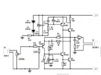
- VR1 10K to 100K Potensiometer
- Bypassed the C1 1uF
- Desoldered R1 47K, R3 10K, C1 100uF, D1(zener diode)
- Replaced C3 220pF with Resistor 10K,
- Replaced R5 470ohm to 1K,
then i tested them and like the improvement
Hi Folks,
I built JHL kit(Chinnese version from Ebay) n then i converted them to JLH(original version), after i tested the amp, stil, i don't like the soundquality of the amp(the top highs/treble rolled off and the bass is weak) so i did some mods again
- VR1 10K to 100K Potensiometer
- Bypassed the C1 1uF
- Desoldered R1 47K, R3 10K, C1 100uF, D1(zener diode)
- Replaced C3 220pF with Resistor 10K,
- Replaced R5 470ohm to 1K,
then i tested them and like the improvement
Attachments
'scuse me, but your mod makes just about zero sense to me.  You now have a considerable output DC offset, roundabout +1.8 V or so. Not something I'd call particularly acceptable. And using a 100k pot will, if anything, only increase noise and distortion.
How did you come to the conclusion of "the top highs/treble rolled off and the bass is weak"? What did you compare the amp to, with what kind of headphones? Have you carried out a basic frequency response test (using e.g. soundcard + RMAA)?
Assuming it is equipped and working correctly, the JLH amp built according to the first schematic should have none of the deficiencies you describe.
You now have a considerable output DC offset, roundabout +1.8 V or so. Not something I'd call particularly acceptable. And using a 100k pot will, if anything, only increase noise and distortion.How did you come to the conclusion of "the top highs/treble rolled off and the bass is weak"? What did you compare the amp to, with what kind of headphones? Have you carried out a basic frequency response test (using e.g. soundcard + RMAA)?
Assuming it is equipped and working correctly, the JLH amp built according to the first schematic should have none of the deficiencies you describe.
Hi there,
I'd like to know if measuring the dc offset with and without load, you see any differences.
because I measure around 30 mv of difference.
My sensation is that DC offset is unstable, and I have some problems to fix it
I changed some components:
C13 = 1,5uF instead of 1uF
R19= 10 K instead of 220K ((no technical choice, only for components availability )
VR3= 2,2 K instead of 10K (idem)
C15 = 47pF instead of 220pF
In this way I extended the range of frequency from 5Hz to 22KHz flat, could it be the cause of my problem?
Thank you in advance
Assuming you have adjusted DC offset to 0+/- 10 mV when the amplifier is warmed up, there should be no significant influence of loading on it. I've simulated with all kinds of transistors, there never was anything more than 1..3 mV of difference to be observed. There shouldn't be one either, since your load connects two nodes at virtually the same potential.
How stable are your supplies?
BTW, try finding a larger-value resistor for R19, otherwise power supply rejection at higher volume settings will suffer.
How stable are your supplies?
BTW, try finding a larger-value resistor for R19, otherwise power supply rejection at higher volume settings will suffer.
I changed psu stage with LM 317/337 instead of 7812/7912.How stable are your supplies?
.
maybe cause of improvvisation wired could generated instable voltage, but don't seem me if I see the multimeter.
http://ubuntuone.com/1nISGLbzDGSr0JKlJTzKrG
How much drift do you get? Some is unavoidable in this concept, as you're essentially seeing 3 B-E voltage drops in series from input to output, their temperature drift included.
If you're seeing more than a few 10 mV even after the amp is warmed up, then you can consider using coupling caps. I'd use two identical 470+ µF caps back to back each, unless you happen to have bipolar ones in 220+ µF, which would be preferred.
If you're seeing more than a few 10 mV even after the amp is warmed up, then you can consider using coupling caps. I'd use two identical 470+ µF caps back to back each, unless you happen to have bipolar ones in 220+ µF, which would be preferred.
I get a drift of 15-20mV
by the way I solved the problem, by mistake I shorted something and now nothing works
so I bought a new JLH.
unfortunately I changed so many components that I was no more able to understand the cause of the high offset.
I didn't understand your whole reply, what does this mean?
thank you!
by the way I solved the problem, by mistake I shorted something and now nothing works
so I bought a new JLH.
unfortunately I changed so many components that I was no more able to understand the cause of the high offset.
I didn't understand your whole reply, what does this mean?
as you're essentially seeing 3 B-E voltage drops in series from input to output,
thank you!
That would be OK.I get a drift of 15-20mV
Can't be much more than a dead transistor, now can it? Those are all dirt cheap (even the TIPs only are about 30 cents) and exact type usually is not particularly critical once you're in the ballpark. Ask the multimeter, the one that's dead short C-E is the culprit.by the way I solved the problem, by mistake I shorted something and now nothing works
so I bought a new JLH.
Simple.I didn't understand your whole reply, what does this mean?
as you're essentially seeing 3 B-E voltage drops in series from input to output,
Referring to the schematic, we find that at DC,
1. Q4 Ic is defined by the voltage drop over R4 and
2. Q4 Ie flows through R7.
Now Ic ~= Ie and R4 = R7, hence the voltage dropping over R7 should be the same as the voltage dropping over R4.
The voltage dropping over R4 in turn is Vbe(Q3) + Vbe(Q1).
Hence the difference between output potential and Q4 base potential is
-Vbe(Q4) + Vbe(Q3) + Vbe(Q1)
and therefore the temperature drift of all three will be seen at the output even if Vb(Q4) is stable as a rock. Only one reason why simple single-ended input stages have gone out of fashion.
Last edited:
Actually significant bias voltage has been found to be detrimental WRT cap distortion, but a bit to counteract Al oxide layer degradation certainly won't hurt.
I just simulated a Death of Zen amp (a creation of Rod Elliott's) which is quite similar in topology except for swapping the current source pnp for an npn transistor. Since it uses bootstrapping to feed the top half of the output stage, I expected lower loop gain, and indeed distortion is about 10 dB worse than in the JLH run at comparable current levels and with the same gain, signal level and 32 ohm load. I'd rather stick with the JLH.
People are using the DoZ with a DC servo, which is something that would also make a lot of sense for a DC-coupled JLH.
Incidentally, it's not hard to modify the JLH to use a complementary output stage. Gets you another 8-9 dB less distortion in this case.
An externally hosted image should be here but it was not working when we last tested it.
Scratch that, this one works even better (~15 dB less distortion than the plain JLH):

Even with the stock values of R2/C3, a preceding volume pot should not exceed 50k, a maximum of 20k is preferred. R2 can still be reduced in value for lower noise if needed.
The intended purpose of the R2/C3 pole is keeping RF out of the amp (longwave and up).
Incidentally, stability with capacitive loads is much improved when removing C5 - R8. The complementary version still starts to struggle at 47n and could probably use a little compensation cap, but the unmodified JLH isn't even stable into 10n in my simulations.
EDIT: I changed the Zobel network C8/R12 to 100n/10R, and that seems to get even the complementary version completely stable.
Distortion in the complementary version is very low indeed, as shown it produces 1.1 Vpp into 32 ohms at 10 kHz with 0.0017% THD (dominant 2nd by a country mile).
Last edited:
It appears Q3 is slightly critical here. Changed that back to 2N2222, et voilà, wonderful stability even with the original R12/C8 combo and no compensation cap on Q3 (in case of the BC337-40, 10p was required). A number of types seem to work well in this position, but BC337 (or BC639) are not among them.
With the 2N2222, distortion into 32 ohms is up somewhat (0.0025%). Actually it was slightly lower than for higher-impedance loads before, must have been a lucky cancellation.
I still didn't bother to reinstate C5/R8. They're not helping stability in any way, AFAICT.
Oh, and R6 in the complementary version is only included for short-circuit protection.
Residual distortion at 11 Vpp (driving a high-impedance load like 600 ohms) appears to be about 0.02%, dominant 2nd as usual. The amp has to be pushed pretty hard for the 3rd to become dominant.
Not bad for a handful of transistors.
Interesting... while the complementary version is a lot less bothered by loads than the plain JLH, its linearity into higher-impedance loads actually is worse. The plain JLH drives 1.1 Vpp into 600 ohms at 0.0004% THD (dominant 2nd), and 11 Vpp at 0.005% (2nd and 3rd about equal). I can only assume that gain via Q3-Q1 surpasses that of Q3-Q2 at higher-impedance loads (R11 probably decreases current source impedance), while with lower ones it is dragged down as Q1's collector resistance drops.
That's using TIP41C models now, btw.
That's using TIP41C models now, btw.
Last edited:
Hi all,
I have built one of these from an Ebay kit. At the moment all the parts are as supplied. It sounds reasonable to me but i've never had a head amp before and don't usually listen to music with headphone so havn't got a reference to compare it to.
My personal taste and main system are more mid forward and open sounding(this perhaps sounds contradictory but is my best interpretation of what i am hearing).
Before i start doing any of the suggested modifications can anyone comment on what difference each makes to the sound ?
Options seem to be:
Better quality electolytics - silmic ? (some or all ?)
Removing some of the film caps bypassing the electrolytics
Changing R1 220k to 47k
Changing R5 470r to 2k2 (reduce gain)
Increasing C4 100uF to 220-470uF
Increasing R9 from 2k2 to 3k3
Increasing R11 from 5r1 to 12r
Increasing C1 from .47uF to 1uF
Removing C5,R8,C8,R12
Better quality pot
Any others ?
I'd also wondered about:
Changing C3 220pF from ceramic to polystyrene
Bypassing the output electrolytic with a film cap
Adding some power resistors betwen the transormer and the board as due to my high mains voltage i have 18V going in and the reg chips seem quite hot
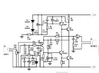
Referring to the modified "JHL" schematic as posted here:
If you build the amp as shown BUT leave out C11-R12 and C12-R14, it should work fine, including good stability. With these components in, it would be prone to oscillation.
What you can do:
Increasing R17/18 lowers gain if needed.
Dropping resistors for the regs. Try ~10 ohms, >=1 W.
When using a better-quality pot, stick with 10k.
Add a 10n..100n (typically 47n) cap across each rectifier diode to suppress RF interference.
Swap C23/24 to bipolar "for good measure". Higher capacity is unlikely to be needed.
Useless:
Increasing the value of C13/15 from .47µ to 1µ does not seem necessary, seeing that simulated FR only is about 0.5 dB down at 10 Hz and there shouldn't be a lot of distortion in this film cap.
The value of R9/10 doesn't make a great difference either way.
The only bypass caps to make any kind of sense here are C17/18 and possibly C30/36 (though I'd think the latter are too far away from the amp to make any kind of difference).
C15/16 (220p) should already be NP0 so no improvement is expected here.
Not recommended:
Only increase R1/2 if you want to reduce idle current / power consumption for some reason. Performance would be expected to become worse, and maximum output current would be reduced.
Advised against:
Do not decrease R19/20 from 220k as this may impair power supply rejection.
- Home
- Amplifiers
- Headphone Systems
- JLH Headphone Amp