from three years ago and still we get Members trying to avoid using the correct two wire Flow and Return connection.
http://www.diyaudio.com/forums/construction-tips/251996-ground-loops.html#post3837304Both the Source and the Amplifier are two channel.
The connection between them is a two channel interconnect.
One interconnect is a two wire connection of Flow and Return. The voltage difference at the Receiver end is amplified and sent to the output.
The other interconnect is also a two wire connection of Flow and Return.
If the returns (Signal Ground) are connected to a common reference at both ends, you have a grounding loop.
The bigger the area in that loop the more interference it will pick up.
It would be really nice if they made a dual coax with the outer of the coax forming an electrically conducting figure 8. That would allow the two returns to have near zero loop area.
I have not seen such a cable, nor have I seen a coax connector that would be compatible with the fig 8 screens.
I suggested that part of the solution would be for Source or Receiver to NOT use a common reference for both channels. I was told "don't be stupid": all Sources have a common Signal Ground reference.
The ground lifting using a resistor (and maybe the inverse parallel diodes) in each Source Signal Ground to Ground reference could maybe be a workable solution.
Close coupling of the two inter connects should help attenuate.
Two forms of attenuation: the ground lifting resistor and the low loop area are better than none.
Certainly a pair of monoblocks solves this, at the cost of separate chassis.
Finally,
the PE connection of the Chassis, or both Chassis, has NOTHING to do with that Signal Return Grounding Loop.
AndrewT, I don't have any issues with your "two wire flow and return" theory if using 2 separate boards that both have a + input and - input for each channel or a single board that uses separate grounds.
In these cases I use a pair of old interconnects that I've whacked in half or twist 2 wires together for each RCA input.
As I stated before, this particular board has only ONE ground connection for the inputs.
Have you even built one of these amps or are you aware of the grounding issues on the outputs? Probably not.
"Three years ago" really has no relevance here to anything as they're probably hundreds of other members who haven't read your post from Feb. 2014.
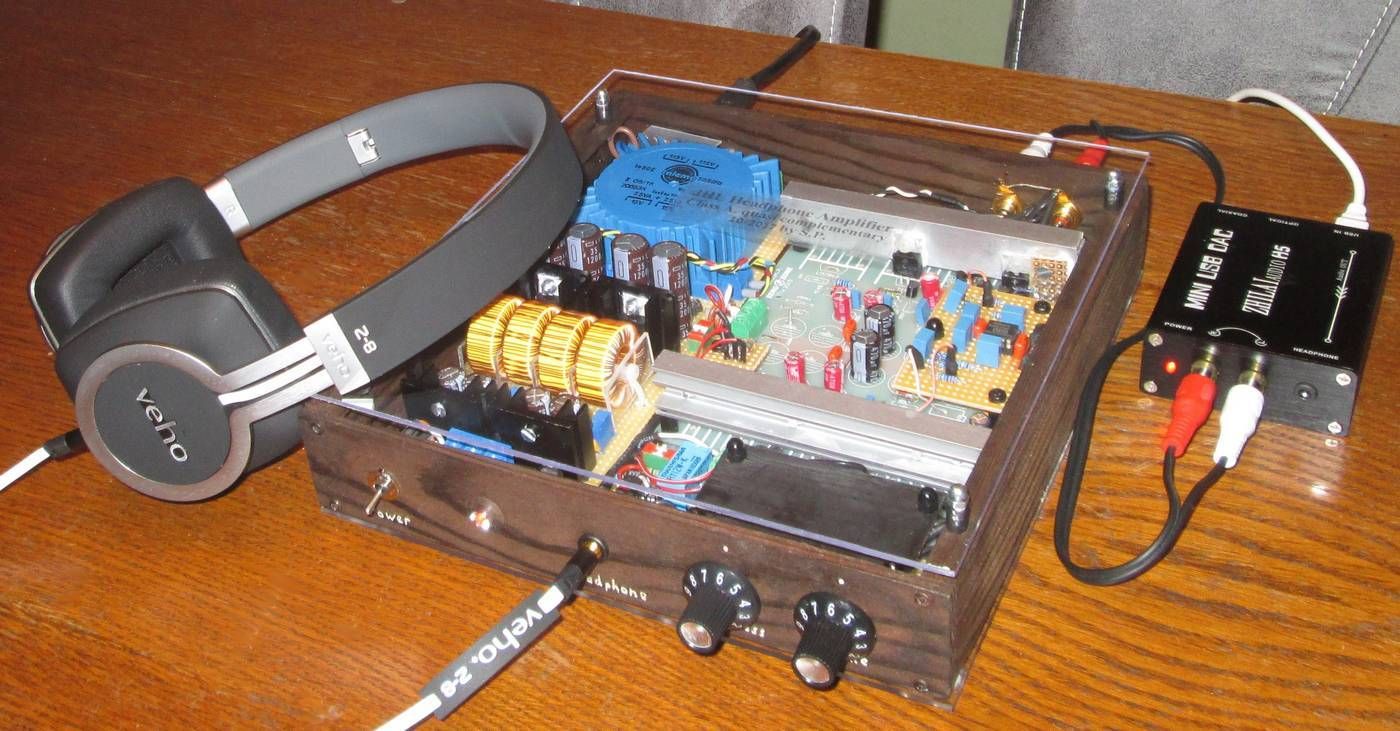
Well, after many tries I gave up on adding the transformer to the JLH1969 PCB and bought the assembled JLH1969 amp
Now using:
Internet Radio > Macbook Pro > TDA1387 x8 > JLH1969 Headphone Amp
Plan to replace the transformer with an Antek AS1212
Have purchased the Servo pcb
Has anyone replaced the JLH1969 potentiometer with an attenuator? Looking at the EIZZ or Dale.
Thank you !
Now using:
Internet Radio > Macbook Pro > TDA1387 x8 > JLH1969 Headphone Amp
Plan to replace the transformer with an Antek AS1212
Have purchased the Servo pcb
Has anyone replaced the JLH1969 potentiometer with an attenuator? Looking at the EIZZ or Dale.
Thank you !
The EIZZ appears to be a very nice stepped attenuator. There doesn't seem to be much feedback about it here on this forum, though.
Why don't you purchase one and report back here with your findings/opinions?
Personally, I would pass on that Dale attenuator you linked to above.
Why don't you purchase one and report back here with your findings/opinions?
Personally, I would pass on that Dale attenuator you linked to above.


Pure Class A Headphone Amplifier AMP 1969 Circuit DIY Kits for HD600 K701 | eBay
is this amp any comparable to JLH??
is this amp any comparable to JLH??
Pure Class A Headphone Amplifier AMP 1969 Circuit DIY Kits for HD600 K701 | eBay
is this amp any comparable to JLH??
No.
how much voltage does the JHL take max that are 12vx2 and 15vx2 etc.
Should read 12V x2 and 15V x 2 etc.?
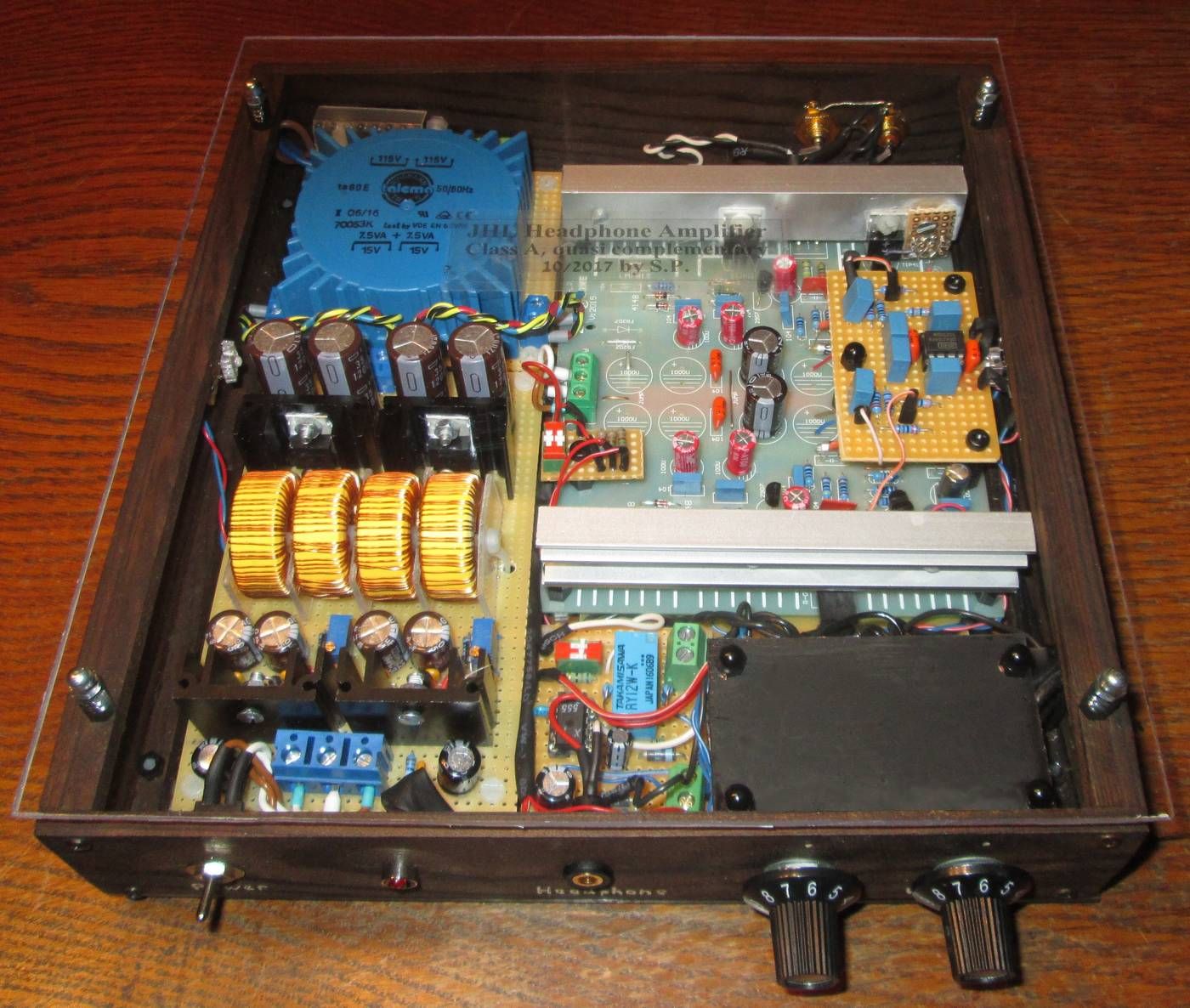
I use a talema 70053k.
Primary: 2x 115V
Secondary: 2x 15 V
2x 7.5 VA (15 VA)
The two 115V primary windings I connected in series and operate the amp at 230 V AC.
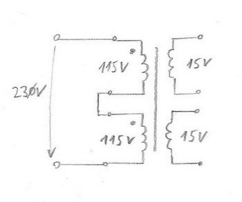
This works perfectly.")
Regards
Steffen
PS: Please note the winding direction (small points in the circuit diagram).
Primary: 2x 115V
Secondary: 2x 15 V
2x 7.5 VA (15 VA)
The two 115V primary windings I connected in series and operate the amp at 230 V AC.
This works perfectly.
Regards
Steffen
PS: Please note the winding direction (small points in the circuit diagram).
Last edited:
Replacing the Zener Diode with 1N4148 Diodes
Hi,
I have just built one of these 'JHL' amps and it's running fine.
The 'JHL' pcb is marked 2V7 for Zener diodes, but 3V Diodes are supplied. Miles Campbell had the same problem a long way back in this thread.
The Zener diode supplied measures 2.91 V in-situ.
Miles Campbell suggested replacing the 3V Zeners with 3 x 1N4148 diodes in series. These measure 2.2V, which is a lot less than the 2.7V I assume Miles was trying to achieve. If I replace them with 4 x 1N4148 in series they measure 2.89V, which is near enough the same as the Zener diode supplied.
Are 3 x 1N4148 or 4 x 1N4148 supposed to achieve 2.7V, and if so how ? HaveI missed something ? Any ideas anyone ?
Thanks
Mark
using standard green LED (Vf=2V) and one 1N4148 (Vf=0.7V) maybe??Miles Campbell suggested replacing the 3V Zeners with 3 x 1N4148 diodes in series. These measure 2.2V, which is a lot less than the 2.7V I assume Miles was trying to achieve. If I replace them with 4 x 1N4148 in series they measure 2.89V, which is near enough the same as the Zener diode supplied.
Are 3 x 1N4148 or 4 x 1N4148 supposed to achieve 2.7V, and if so how ? HaveI missed something ? Any ideas anyone ?
Thanks
Mark
- Home
- Amplifiers
- Headphone Systems
- JLH Headphone Amp