Thank you!
I found what the problem was with my amplifier. I used BC212 transistors as a E-B-C, but there are two kinds of BC212. My ones are C-B-E. Damn! Fortunately, after I changed the polarity, the amp got up well. Its temperature is very good, and the bias current is about 100mA (R11=4,7ohm). But you were right. I got +0,9volts at the output But I am still happy to have a well-operating amplifier There remains no more but to find out the solution how to get 0V at the output.
ps.:Sorry for my bad english, it's not my native.
I found what the problem was with my amplifier. I used BC212 transistors as a E-B-C, but there are two kinds of BC212. My ones are C-B-E. Damn! Fortunately, after I changed the polarity, the amp got up well. Its temperature is very good, and the bias current is about 100mA (R11=4,7ohm). But you were right. I got +0,9volts at the output
But I am still happy to have a well-operating amplifier There remains no more but to find out the solution how to get 0V at the output.ps.:Sorry for my bad english, it's not my native.
Hi, I gave you the solution to fix the output dc voltage.
Just use a pot for R4 . Or use a fixed resistor in parallel with a variable pot.
Like say a 10 K resistor in parallel with a 10 K preset. Set it to give 4.7K ( measured with a DMM with power off) and then adjust it with power on to give you < 1mV at the output.
Can you post any pictures ? How does it sound ? My board isn't ready yet.
Last edited:
Hi, I gave you the solution to fix the output dc voltage.
Just use a pot for R4 . Or use a fixed resistor in parallel with a variable pot.
Like say a 10 K resistor in parallel with a 10 K preset. Set it to give 4.7K ( measured with a DMM with power off) and then adjust it with power on to give you < 1mV at the output.
Can you post any pictures ? How does it sound ? My board isn't ready yet.
I tried to use a 11,52K for R4 instead of 4,7K. Output DC was nearly 0V, but it was changing slowly. Starting from +13mV to -12mV, then up to about +10mV again, and back
It took minutes, not seconds.Using 12K R4 it was -40mV, with 10K it was +100, so I will really need a potmeter. The problem is that the voltage is not fix, it is changing.
I don't expect the dc to stay fixed.It's referenced to base emitter voltages and diode drops. These are not in physical contact with each other and hence not varying by the same amount ( deg C ).So dc will vary from the set point. Best to set it ( several times) after 30 minutes of power on. It might have a reduced variation. Varying isn't the problem. Varying too much is the issue. I wanted the diodes to be mounted on the same heatsink as the output devices. Unfortunately I am getting no spare time to finish my pcb ! I hope this weekend is good.
Done any listening tests yet ?
Done any listening tests yet ?
I don't expect the dc to stay fixed.It's referenced to base emitter voltages and diode drops. These are not in physical contact with each other and hence not varying by the same amount ( deg C ).So dc will vary from the set point. Best to set it ( several times) after 30 minutes of power on.
Done any listening tests yet ?
I changed the circuit to set the DC to zero. I use a 10K pot, not a 4,7k.
It seems to work. I can set the DC to be about zero, but it's changing a bit. After a long it moves slightly, max. 1-2mV. But the heatsink is very hot. It's not a small one, so I don't know if it's normal or not. And the heatsinks on the 7812/7912 are very hot, too. Maybe the 4,7ohm R11 is too low? But as I measured, the offset is 110mA, and the stab ICs are 2A ones.
Attachments
Sorry, I haven't recognized this question. After I set the zero DC, I listened how it sounded. I soldered the C1 cap to the ground, plugged the headphone(a cheap one). I was surprised because I was able to hear some odd sound from it.Done any listening tests yet ?
A sound, like hum but not just a hum, I also heard a "bzz" effect, as if I searched a channel on an old radio. Also, when I touched the ground, or grazed a metal to another one (not in the amlifier, just beside it), it confused the sound, as if there was no ground-shield (on the input cable), but there was of course. So I was afraid of listening it too long, but I connected an MP3 player to the input to see whether it sounded or not. It sounded very well, and the volume was quite enough, maybe too much
The bass was very impressive, but there was noise among the music sounds.So I still have to work on it to find out what the problem is. Any idea?
I will try to rig up my board by tomorrow. Will let you know what happens then. I might add that you need to be careful how all the ground routing is done. Low level ground must not 'ever' carry/share any dc supply path. That can give you hum and buzz.
Is your amp grounded to the metal chassis ? Is the chassis grounded to mains earth. Sounds like the ground/chassis is floating.
About running very hot.
The heatsinks might not be enough. This circuit dissipates twice the amount of power than my single supply circuit. You can increase the 4.7 ohm resistor to decrease the quiescent current. Try 6.8 ohms. Any drawing or picture of the heat sink you have used ?
Last edited:
I will try to rig up my board by tomorrow. Will let you know what happens then. I might add that you need to be careful how all the ground routing is done. Low level ground must not 'ever' carry/share any dc supply path. That can give you hum and buzz.
Is your amp grounded to the metal chassis ? Is the chassis grounded to mains earth. Sounds like the ground/chassis is floating.
About running very hot.
The heatsinks might not be enough. This circuit dissipates twice the amount of power than my single supply circuit. You can increase the 4.7 ohm resistor to decrease the quiescent current. Try 6.8 ohms. Any drawing or picture of the heat sink you have used ?
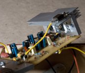
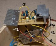
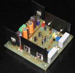
Here are some picture.
The chassic is wooden.
"Low level ground must not 'ever' carry/share any dc supply path." I don't understand this sentence. What do you mean? What am I supposed to do?
Anyway I tried to grounded it to the earth, but it didn't help. As you can see I connected the heatsink to the ground, no success. Not to say, since I did it, It has made a noise when I touch the heatsink with any metal.
I have recorded the sound effect from its output. I hear that when the 'Left' output cable draws close to the 'Right' cable, or if the headphone cable writhes (spiral).
Attachments
OK , you have oscillations !
It might be due to the way things are connected . Check any capacitive coupling ( due to close wires ) between output and input. Note that it could be RF oscillations with spurious products in the audible range. RF oscillation could be due to the circuit !
Let me rig up my board and see if I get a similar thing.
Last edited:
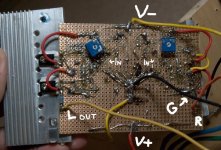
Check any capacitive coupling ( due to close wires ) between output and input.
The input and output are far away from one another as it is seemed in the picture I attached.
But, maybe, I found the source of the problem. I bought the C5 capacitor as a 330pF, but at home I recognized that it was only a 33pF, because the text on it is '33'. I will try to get a truly 330pF and see whether it solves the oscillation or not.
I hope your amp will be all right
Good luck!Attachments
I think you might have to look elsewhere. Maybe even the power supply ?
In my sim of the circuit 33pF does not show up any problems . All transistors are BC5XX and BD136 output . I didn't really think the 33pF caused the problem as it would just oscillate and not whistle with a variable frequency like it is doing now. It's like a signal generator , sweeping over the full audio band !
It's taking me a long time to do the board layout and its only 90% done. Hope I get it done today. It has an on board psu.
Hi Melorin,
Did you solve the problem ? I find in the sim that the square wave response is unstable with the component values you have. So maybe it's oscillating. The feedback cap and the zobel keep the amp stable with a capacitive load. I used 1000pF (parallel with 32 ohms as load ) for a long ( shielded ) cable. Many cables here are about 120pF per meter. So component values need to be picked for a stable operating point.
My headphone amp uses slightly different component values and the ones I have may not be as suitable for you. However my feedback from output to the input transistor has a 3.3K ohm resistor parallel with a series 10 ohm and 47 pF. The Zobel is 22 ohms with 0.1uF . Some component values I selected because that's what I have right now !
My board is finally ready , BUT I discovered that I etched it with a reversed pattern .....not again !
Luckily the transistors can be reversed. However the heatsink will now have to be within the board unless I flatten the power devices. So until I have some heatsinking I cannot power it up. Today is a busy day. Hope I get some time later this evening.
Did you solve the problem ? I find in the sim that the square wave response is unstable with the component values you have. So maybe it's oscillating. The feedback cap and the zobel keep the amp stable with a capacitive load. I used 1000pF (parallel with 32 ohms as load ) for a long ( shielded ) cable. Many cables here are about 120pF per meter. So component values need to be picked for a stable operating point.
My headphone amp uses slightly different component values and the ones I have may not be as suitable for you. However my feedback from output to the input transistor has a 3.3K ohm resistor parallel with a series 10 ohm and 47 pF. The Zobel is 22 ohms with 0.1uF . Some component values I selected because that's what I have right now !
My board is finally ready , BUT I discovered that I etched it with a reversed pattern
.....not again !Luckily the transistors can be reversed. However the heatsink will now have to be within the board unless I flatten the power devices. So until I have some heatsinking I cannot power it up. Today is a busy day. Hope I get some time later this evening.
Hi Melorin,
Did you solve the problem ? I find in the sim that the square wave response is unstable with the component values you have. So maybe it's oscillating. The feedback cap and the zobel keep the amp stable with a capacitive load. I used 1000pF (parallel with 32 ohms as load ) for a long ( shielded ) cable. Many cables here are about 120pF per meter. So component values need to be picked for a stable operating point.
My headphone amp uses slightly different component values and the ones I have may not be as suitable for you. However my feedback from output to the input transistor has a 3.3K ohm resistor parallel with a series 10 ohm and 47 pF. The Zobel is 22 ohms with 0.1uF . Some component values I selected because that's what I have right now !
My board is finally ready , BUT I discovered that I etched it with a reversed pattern
Luckily the transistors can be reversed. However the heatsink will now have to be within the board unless I flatten the power devices. So until I have some heatsinking I cannot power it up. Today is a busy day. Hope I get some time later this evening.
I've given up. I have no more idea how to shut down the oscillation.
Furthermore, I have a new guest in my amp beside oscillation, low level hum, like the transformator would be heard, but the power supply is very good and is seperated from the amplifier.
OK I finally finished the board and assembly. One channel seems to have a problem. I'm sure I made a mistake somewhere becaused I reversed the board layout ! I'll fix it tomorrow.
However the other channel works. I'm able to set the dc output to around +/- 1mV . The meter reads 0.000 V . It didn't change for about 1 hour that the amp was on. Will have to look at this closely tomorrow. I did set the dc offset after a 30 mins warm up period.
Frequency response was flat ( 0dB ) at 20 Khz and -0.2db at 20 Hz with a 33 ohm load. Max output ( 1% dist ) was about 3 Volts rms into 33 ohms.
Max output into 10 K ohms load was about 7 volts rms( less than 0.1% dist).
Second harmonic was at -74.2 dB and 3rd harmonic at -75.8 dB. All other harmonics were at -95dB or below.
Pity the second channel had a problem. I couldn't listen to it. Note that I'm getting a higher level of 3rd harmonic distortion now. The single supply unit had practically only second harmonic distortion. Must try to see why that is so. The noise floor is also very low and you can hardly see any power supply harmonics ! So there should be no hum on the can's.
The heat sinks do heat up but I didn't measure the temperature. Quiescent current appears to be at about 0.1A in the output stage.
Looks good so far. Will have to do a listening comparison with the single supply unit also.
Attachments
Last edited:
Thanks Kenpeter.
I will be doing the comparison test ( between single supply and split supply )sometime this weekend I think.
I didn't mention that the output impedance was less than 0.25 ohms and since there was a series resistor of 2.2 ohms the Zout is about 2.45 ohms. No problem for most headphones. Response errors due to varying headphone impedance should be under about 0.25dB.The 2.2 ohms is for stability under capacitive loading. You could reduce it to 1 ohm if required and check for stability.
If anyone wants to see the actual performance graphs, please tell me now. I could put them up. If no one is interested in them I'll just mention my findings regarding the sound and close this thread. Need to move on to other things !
Cheers.
Which version did you build? Is the potmeter for the 0 DC instead of R4? Could you show us the schematic of power supply? I try to find out why I have hum.I'm able to set the dc output to around +/- 1mV . The meter reads 0.000 V . It didn't change for about 1 hour that the amp was on. Will have to look at this closely tomorrow. I did set the dc offset after a 30 mins warm up period.
Could it be the problem that I have +11,7V and -12,1 voltages at the power output?
Which version did you build?
The one with the split supplies. The red LED is used in place of D3 / D4.
...Is the potmeter for the 0 DC instead of R4?
Yes the potmeter is used in place of R4. I used a 10 turn preset as I had that.
10 K ohms.
Could you show us the schematic of power supply?
I'll describe the power supply as it's easier than drawing it out now.
The transformer with 12 - 0 - 12 V secondary is connected to a bridge made up of four FR107 diodes. The positive rail feeds a 2,200uF capacitor. This is connected to the next 2,200uF cap via a 2.2 ohm resistor ( 1 watt). That filters a bit of the psu noise. This is followed by a LM7812 which has a 47uF capacitor at its output. The negative rectified rail is connected to a similar circuit using a LM7912 to give -12 V.
Could it be the problem that I have +11,7V and -12,1 voltages at the power output?
The voltages I have are + 11.8 V and -12.05 V after the LM regulators.
Are you using the same values for all parts as shown in the circuit diagram you posted?
The listening test !
I finally got to hear the new phones amp with the split supply. It sounds great ! The two main headphones I used were the Sennheiser HD580 and the Philips SHP 8900.
The HD850 sounds less bright than the 8900 but transient drums sound much tighter and powerful on it. The 8900 does go a bit lower than the HD580 and it's just about audible on some tracks. The HD850 sounds dull if you go from the 8900 to the 580. But the HD580 probably sounds smoother in the mid range. The image however is a bit flat. The 8900 sounds spacious !
I compared the single supply amp with the split supply amp. They sound quite similar. Especially with the Sennheiser ( 600 ohms). With the 8900 ( 32 ohms) the low end is slightly lighter but not very easily noticeable on the single supply amp. Transients are just as tight on both amps and I couldn't hear much of a difference in the mid range or HF. No audible hum or hiss on either amp.
The single supply version is safer than the split supply version because you have a ( usually horrendous!) electrolytic capacitor in series with the signal path. However unlike many locations this one is biased at a high 6 Volts dc and so maybe performs better than no bias or low biased elcos.
Main thing is that a crashed amp will not burn up an "expensive" pair of headphones. No series relay in the low current signal path and no dc servo which is frowned upon by many.
The split supply comes out ( slightly) ahead just because there is no capacitor in the output and just about noticeable on the 8900's 32 ohms load. DC offset shift drifted by about 1mV either way over a 2 hour period. Switch on from cold produced about 25 mV offset which settled down to about 4mV in about 2 minutes and 1mV in 5 minutes.
I would still prefer to have a shorting relay ( to ground) in case of dc offset error with an opamp to detect a dc offset of more than 5mV or 10 mV(?). That would protect the "expensive" can from going up in smoke in case the power transistors fail ( very unlikely I'd say but then Murphy is always lurking around the corner !)
If anyone wants any clarifications etc I'd be happy to reply.
Apart from that I'm ending this thread. I completed what I was out to find out and hope it helped all those who have been following the progress.
Melorin please contact me via PM .
I sat down and listened to several albums after my last post. The amp sounds really very nice. So if given a choice build the split supply one.
Maybe you could add a parallel relay protection if you really plan to use it all the time and with expensive headphones.
On switch on you do get a 0.5 volt surge which lasts a couple of seconds. Switch off also produces a surge. Maybe the phones need protection at that time ? Even if you plug the phones in after a while and remove it before power down, you could forget sometimes !
I'll check the dc surge on my scope later on.
Certainly sounds better than a power boosted opamp circuit using OPA2134 and TO126 type power transistors. I'm really glad that I tried out this amp. It just happened because of the new 'Headphones' section !
- Home
- Amplifiers
- Headphone Systems
- JLH Headphone Amp