Always happy to help. I would recommend you actually listen to the JLH headphone amp, after all, that's what its for. Check your dc offsets are below 10mV and plug in your cans. This will give you a sonic starting point before you make any further changes that might actually degrade the sound. In fact, I would listen to it for several days before making any other changes. If you plan to use LT1083 low drop-out regulators with 20VDC supplies shown on your schematic, I recommend you fit 4R7 - 10R 3W resistors in the supply lines before the on-board psu filter caps. I fitted 3R3 resistors conveniently into supply lines using the vacant bridge diode positions, feed from an external separate 18V dual supply. The resistors reduce the heating of your regulators but more importantly provide welcome additional mains ripple rejection on the supply.
Thanks.
I'll test the headamp with a pair of IEM's before hooking up my X2's.
You mean set the LT1083 vregs at a higher voltage and bring it down with a series resistor?
I have yet to figure out where best to hook up power supply wiring on the PCB when removing the 7812/7912.
Was about to finish a module or two of the modular DAC that's going to provide the signal for the headamp (this one and the two other I'm working on) when my solder station died after almost ten years of use.
Fortunately my fiance said I could have one as an early birthday present
I've ordered the Weller WHS40D, not fancy but it is a known brand and should be of good quality.
So, no diy until next week when I get the new solder station...
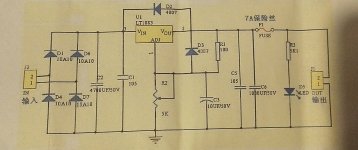
No, the dropper resistors are fitted before the LT1083 regulators on the unregulated side. The LT1083 only needs about 1.5V drop as opposed to 3V for standard 78/79XX regulators so you can reduce ripple and heat dissipation with a high watt low value resistor. You set up the feedback resistors on LT1083 to give the same 12V output as before. Another little trick is to add a 10 - 47uF cap on the ADJ pin to add a few more dB's of ripple rejection.
I'll check the schematic, but iirc the boards I've got has a 10uF there. As well as 4700uF and onboard rectifying.No, the dropper resistors are fitted before the LT1083 regulators on the unregulated side. The LT1083 only needs about 1.5V drop as opposed to 3V for standard 78/79XX regulators so you can reduce ripple and heat dissipation with a high watt low value resistor. You set up the feedback resistors on LT1083 to give the same 12V output as before. Another little trick is to add a 10 - 47uF cap on the ADJ pin to add a few more dB's of ripple rejection.
So for me it's a matter of removing PS parts from the PCB and find the best place to attach wires from the dual LT1083 boards.
I don't use the lytics supplied with the kit though as I don't trust them.
Found the schematic for the LT1083 vreg.
Tried hooking up the DC-servo board today, didn't work, so I don't have the values right for it yet.
Trimming DC offset with 110R dummy loads atm.
I'm below +/-5mVdc, but it has not yet quite stabilized.
Most of the time I'm under +/-2mVdc.
Tried hooking up the DC-servo board today, didn't work, so I don't have the values right for it yet.
Trimming DC offset with 110R dummy loads atm.
I'm below +/-5mVdc, but it has not yet quite stabilized.
Most of the time I'm under +/-2mVdc.
Attachments
They build a better headphone amp
Well I hope the one I'm perf boarding will be better
Or the AD797+BUF634 I'm collecting parts for..or maybe a design around one or two ecc86?
Lol, I've got enough ideas atleast.
I discovered a rather nasty glitchy connection in the knock-off neutrik HP jack. GND connection was very poor, I had to wiggle the 6.3mm to 3.5mm adaptor to get it to connect.
I've ordered a few, different kind, new 6.3mm panel mount HP jacks.
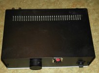
While waiting for those, and for my new solder station without which I can't do a thing(feel disabled lol), I've put the top on the enclosure.
I know there's a small gap on the backside, it's by necessity as the R-core wont fit otherwise...it might even add extra cooling
I've ordered a few, different kind, new 6.3mm panel mount HP jacks.
While waiting for those, and for my new solder station without which I can't do a thing(feel disabled lol), I've put the top on the enclosure.
I know there's a small gap on the backside, it's by necessity as the R-core wont fit otherwise...it might even add extra cooling
Attachments
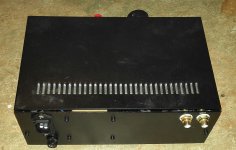
Looks neat and functional but it wont work because it doesn't have a Power LED on the front panel
Darn, I forgot to put in the most important part...
I've got a B1 pre-amp and a new build in the works, so I'm set for pre-amps
Hi guys I just received an assembled JLH headphone amp from Enjoy in your hi-fi project, diy tube amp, amplifier diy, amp diy. I am looking at the schematic from this thread and trying to understand it before digging up the new board. For the most part I understand the R19/20, R21/22 changes to achieve a "better" bias point, one that can be tuned with a fine adjustment with the pot. I dont understand the R9/R10 change from 2k2 to 3k3. This has absolutely no effect on the base current into Q1.
That's more like 330 µF if you want to accomodate 32 ohm phones, 680 for 16 ohms. And that's without the rule of thumb of oversizing electrolytics by a factor of about 10 or at least 5 in order to minimize bass distortion introduced by the cap. You can probably imagine that things are getting a tad bulky at this point. Plus, you may want to have a bipolar (or the DIY version, two polars back-to-back) if offset can swing both ways - don't forget to take signal amplitude into account.Also why is there so much emphasis on getting the zero dc bias point at output. Can we just put a capacitor(around 30uF or so) at output. That way DC is blocked and the effect on AC signal is negligible. Atleast in my simulations I dont see a different in the gain.
So you're possibly looking at two 1500-6800 µF 16-25+V per channel. You can probably tell why speaker amps generally got rid of output coupling caps decades ago.
When the PS required is dual AC does it mean 2 rails each for +V, 0 or one each of (+V,0) & (0,-V) . This is the board I am referencing JHL Class A headphone amplifier pre-amp assembled board - $38.80 : Enjoy in your hi-fi project, diy tube amp, amplifier diy, amp diy
I just got a 15V, 10VA Antek toroid to go with this and am unsure of the connections.
I just got a 15V, 10VA Antek toroid to go with this and am unsure of the connections.
The transformer either needs to have two 15V~ secondaries or one 15-0-15V center-tapped.
Is it an AN-0115? That one is of the first type, so it's basically OK.
Going by their wiring diagram, you need to join one blue and one green wire, but obviously not those of the same winding, so make sure there's no ohmic connection between them.
On the amplifier board, the joined wires go in the GND connection, while the remaining two are hooked up to the ACs.
Twisting all of the wires together is not totally necessary here but recommended.
And that's pretty much it.
You usually want to orient the side with the primary-side wiring going in facing away from your electronics.
Speaking of primaries, I am guessing you could hook those up in parallel (same color wires) though I'm not sure how much of a difference it really makes.
Is it an AN-0115? That one is of the first type, so it's basically OK.
Going by their wiring diagram, you need to join one blue and one green wire, but obviously not those of the same winding
, so make sure there's no ohmic connection between them.On the amplifier board, the joined wires go in the GND connection, while the remaining two are hooked up to the ACs.
Twisting all of the wires together is not totally necessary here but recommended.
And that's pretty much it.
You usually want to orient the side with the primary-side wiring going in facing away from your electronics.
Speaking of primaries, I am guessing you could hook those up in parallel (same color wires) though I'm not sure how much of a difference it really makes.
sgrossklass yes it is the AN-0115. I was thinking of connecting both greens together to ground on board and then blue, one each to AC input. That is not a valid connection ? The board needs the 2 AC voltages out of phase ?
Primaries, I thought each primary feeds one secondary but you seem to be saying that one primary can feed both secondaries. Hmm.
Primaries, I thought each primary feeds one secondary but you seem to be saying that one primary can feed both secondaries. Hmm.
- Home
- Amplifiers
- Headphone Systems
- JLH Headphone Amp