One thing you have forgotten was to protect your regulators with a diode over each providing a discharge path for the 2200uF capacitors into the 100uF input capacitors.
Normally the higher value capacitor would be placed at the input of the regulator.
Just an observation.
Yes, I know.
Kind rushed the temporary lm3x7 dual rail supply together when I got my Fidelio X2's and really loved the sound. Only source I have atm is the PC motherboard soundcard, I have one BCL clone being operated on (or scrapped depending on this headamp and the one I'm perf boarding).
I'll probably use LT1083 dual rail supply for this headamp.
Just waiting for the PCB's, I have one perf boarded but it's too bulky.
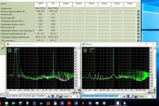
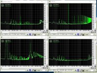
thank you on answer, i have sold my good usb recording soundcard and this is measuring with motherboard intergrated card and cheap 3.5mm cable so i dont know how to get noise down but thats why i measured my ne5532 output in same condition , so there is that harmonics over 1k that is problem,i hear them as cheap cartridge sound. i am using unknown power diodes in bias and general purpose transistors but 1k is not that high so its puzzling me.
Started over on the "JHL" headamp.
Populated PS part of the PCB except for rectifying diodes.
Swapped back to Zeners, 2V7 as on the silkscreen.
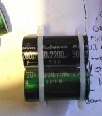
I put two Rubycon ZLH 470uF/25V in series( + - - + ) on each output.
I figured I'd get it working like this before making modifications to it.
Hopefully I'll have time to power it on at measure DC offset etc today.
I have one 100nF Wima left to solder to the PCB.
The large-ish first to lytics are 2200uF Elna RJH's
I just noticed that I need to swap PS wiring, red and white wires are in the wrong spot. Further proof that I should step away from the solder station when getting too tired to think...

Populated PS part of the PCB except for rectifying diodes.
Swapped back to Zeners, 2V7 as on the silkscreen.
I put two Rubycon ZLH 470uF/25V in series( + - - + ) on each output.
I figured I'd get it working like this before making modifications to it.
Hopefully I'll have time to power it on at measure DC offset etc today.
I have one 100nF Wima left to solder to the PCB.
The large-ish first to lytics are 2200uF Elna RJH's
I just noticed that I need to swap PS wiring, red and white wires are in the wrong spot. Further proof that I should step away from the solder station when getting too tired to think...

What impedance are your headphones?
The 470+470uF output caps are effectively 235uF
That is very low and would only suit high impedance headphones (>100ohms).
Ahh, I did not know that was the way to calculate it.
I'll need to use bigger caps then as I have the Philips Fidelio X2's
30ohm
100dB/mW
5-40000Hz
If that claimed 5Hz were actually achievable, you can use that to arrive at the required capacitance.
F-3dB = 1 / (2 Pi R C)
Therefore C = 1 / (2 * Pi * R(impedance) * F-3dB)
C >= 1 / 2 *3.14*30ohms*5Hz >= 0.00106uF
For two polar capacitors in series, that comes to 2.12milli Farads, therefore use two 2200uF
That should give pretty good bass response down to 20Hz, since the F-3dB of the capacitor filter is two octaves below what you can hear.
You could instead use 4 off 1mF caps, +--+ in parallel to -++-
The that still gives the bipolar effct since it uses back to back and doubles the series capacitance since two sets are in parallel.
4 off 1mF used in series parallel comes to an effective 1mF.
1mF 16V, or 25V, are very cheap. I have bags of 50, or 100 of each.
Last edited:
By coincident I am working on this right nowIf that claimed 5Hz were actually achievable, you can use that to arrive at the required capacitance.
F-3dB = 1 / (2 Pi R C)
Therefore C = 1 / (2 * Pi * R(impedance) * F-3dB)
C >= 1 / 2 *3.14*30ohms*5Hz >= 0.00106uF
For two polar capacitors in series, that comes to 2.12milli Farads, therefore use two 2200uF
That should give pretty good bass response down to 20Hz, since the F-3dB of the capacitor filter is two octaves below what you can hear.
You could instead use 4 off 1mF caps, +--+ in parallel to -++-
The that still gives the bipolar effct since it uses back to back and doubles the series capacitance since two sets are in parallel.
4 off 1mF used in series parallel comes to an effective 1mF.
1mF 16V, or 25V, are very cheap. I have bags of 50, or 100 of each.
")
Attachments
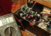
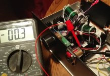
Got this headamp powered up today.
With the 2* 2200uF caps in series on the outputs, I got the offset down to < 1mV.
The heatsinks get hot, not too hot for touching, but very hot.
I'll leave the headamp running for a couple of hours tomorrow and make sure it is stable.
With the 2* 2200uF caps in series on the outputs, I got the offset down to < 1mV.
The heatsinks get hot, not too hot for touching, but very hot.
I'll leave the headamp running for a couple of hours tomorrow and make sure it is stable.
Attachments
How quickly does the offset voltage drop for those of you that has used capacitors on the output?
It takes a while for mine, even with 110R resistors as dummy loads.
Without the dummy loads, it takes in the area of 10min - 15min or so for the DC offset to drop to somewhat acceptable levels.
As output capacitors I used 2x 2200uF in series for 1100uF.
It takes a while for mine, even with 110R resistors as dummy loads.
Without the dummy loads, it takes in the area of 10min - 15min or so for the DC offset to drop to somewhat acceptable levels.
As output capacitors I used 2x 2200uF in series for 1100uF.
The output capacitor would reach it's charged state around the time the Sun blows up.
But, it gets to within a couple of percentage points in 10 times it's RC.
A 1100uF (two 2200uF in series) feeding into a disconnected headphone with a 110r grounding resistor will charge to ~63% in one RC.
RC = 110ohms*0.0022uF = 0.24seconds. 10*RC = 2.4seconds.
If your starting voltage offset is 1Vdc and stays at 1Vdc, then after 2.4seconds the offset after the DC blocking capacitor will be <0.01Vdc.
Since your offset is lower than 1V, you should find that your offset without the headphone connected should be <<10mVdc in ~2.4seconds.
If you switch on, or switch off, with the headphones connected, then the lower resistance will shorten your charging/discharging RC.
I think you have measured it incorrectly, or wired it incorrectly.
The output capacitor would reach it's charged state around the time the Sun blows up.
But, it gets to within a couple of percentage points in 10 times it's RC.
A 1100uF (two 2200uF in series) feeding into a disconnected headphone with a 110r grounding resistor will charge to ~63% in one RC.
RC = 110ohms*0.0022uF = 0.24seconds. 10*RC = 2.4seconds.
If your starting voltage offset is 1Vdc and stays at 1Vdc, then after 2.4seconds the offset after the DC blocking capacitor will be <0.01Vdc.
Since your offset is lower than 1V, you should find that your offset without the headphone connected should be <<10mVdc in ~2.4seconds.
If you switch on, or switch off, with the headphones connected, then the lower resistance will shorten your charging/discharging RC.
I think you have measured it incorrectly, or wired it incorrectly.
I wired and measured the output like this.
An externally hosted image should be here but it was not working when we last tested it.
The sch you have shown is correct.
The two series connected capacitors have an effective capacitance of 1100uF
The C combined with the R creates an RC time constant of 0.24seconds.
Your red and black probes are touching the correct measuring points.
Your very long delay measurements do not make sense.
Some else is not right.
Is the sch really the way you have wired it up?
The sch you have shown is correct.
The two series connected capacitors have an effective capacitance of 1100uF
The C combined with the R creates an RC time constant of 0.24seconds.
Your red and black probes are touching the correct measuring points.
Your very long delay measurements do not make sense.
Some else is not right.
Is the sch really the way you have wired it up?
Yes that is the way it is wired up, but the resistors are soldered to two RCA jacks at the end of a Y-cable (between pin and gnd).
This way I can use the load for more than one headamp project.
I've temporarily soldered a 4700uf in series with a 1K resistor between each rail and GND to check that the 7812/7912 are putting out correct voltages.
I'll probably get around to measuring voltage across the those resistors today. to see if there's an uneven supply or something causing the drifting offset. (Thanks Mooly for the suggestion, and all advice).
maybe the "Y" is not wired as you think.
Short test aka buzz test with the DMM does give signal between the right places.
It's a common 3.5mm stereo to 2x RCA Y-cable that I put RCA females in with the resistors between pin and gnd for each channel.
I think that is correct anyway?
Hi Mayday,
Im listening to my JLH Class A amp as we speak, using a Sansa Clip+ and Seinnheiser HD565 Ovation headphones, sounds great with the mods discussed earlier in this thread. Maybe you are making this too complicated with output caps etc. Usually less is better in audio. You should be able to adjust the output offset to less than 5mV and lose the huge caps. If nothing else, try to find out why there is a large offset, that is more likely a fault elsewhere. I will help too if you need it.
Im listening to my JLH Class A amp as we speak, using a Sansa Clip+ and Seinnheiser HD565 Ovation headphones, sounds great with the mods discussed earlier in this thread. Maybe you are making this too complicated with output caps etc. Usually less is better in audio
. You should be able to adjust the output offset to less than 5mV and lose the huge caps. If nothing else, try to find out why there is a large offset, that is more likely a fault elsewhere. I will help too if you need it.- Home
- Amplifiers
- Headphone Systems
- JLH Headphone Amp