Very nice photography.
I wonder how hot it gets inside after half an hour, and with the lid closed ??
Bias should be 250mA for 2 channels, correct ?
That means 6W dissipation with no ventilation or direct thermal coupling to the aluminium case.
Patrick
Thank you!
") The amp indeed generates quite a lot of heat which can be a problem. Therefore I added ventilation holes on top. Attaching the TIP41c’s to the cabinet could be an option as well.
The amp indeed generates quite a lot of heat which can be a problem. Therefore I added ventilation holes on top. Attaching the TIP41c’s to the cabinet could be an option as well. In theory, if the amp produces 6W, and is on for one half hour, it produces 6*60*30 = 1.08E01 kJ of heat. The dimensions of the cabinet are 0.22 * 0.0515 * 0.165 = 1.87E-3 m^3. The density of dry air is 1.3 kg*m-3, so there is approximately (ignoring the intestines) 1.3 * 1.87E-3 = 2.43E-3 kg of dry air in the cabinet. The specific heat of dry air is 1.0 kJ/(kg*K). So, to raise the temperature of 1 kg dry air, one needs 1 kJ. To raise the temperature of 1.87E-3 m^3 by one K, one needs 1*2.43E-3 = 2.43E-3 kJ of energy.
Thus 1.08E01 / 2.43E-3 kJ = 444.4 K raise in temperature. Of course, heat will radiate and the PCB and aluminium will absorb some of the heat as well. In practice temperature raise will be significantly less, so fortunately the intestines will not melt
.And I have to wonder why no one actually built the complementary version (Circuit 2) :
The Class-A Amplifier Site - JLH Headphone Amplifiers
If anything, it is much simpler (ignore the circuit around Q3,4 which is just for bias stabilisation).
And it has less even harmonics.
Just because of lack of cheap PCBs ??
Patrick
The Class-A Amplifier Site - JLH Headphone Amplifiers
If anything, it is much simpler (ignore the circuit around Q3,4 which is just for bias stabilisation).
And it has less even harmonics.
Just because of lack of cheap PCBs ??
Patrick
Thank you!
If you add vent holes to the top ... you have to add vent holes to the bottom or else where is the air gonna come from?

Drill right over top and bottom of the heatsink fins, and then add some drill hole to the pcb to get great airflow!
You've done exactly what I wanted to do, add a servo for DC and Case It!
Beautiful!
Cheers,
Jeff
Last edited:
So you have not measured ?
Patrick
I've just conducted some temperature measurements after one hour power on by adding a thermocouple inside the cabinet. The ambient temperature at this moment is 22 degrees C, the air inside the cabinet reached ~37 degrees C (delta T = 15 degrees). I've had to unscrew the top to get a proper measurement of the heatsinks. Although this was done within a minute, during that process some of the heat possibly radiated away. The heatsinks were measured with an IR thermometer. The TIP41c heatsinks reached approximately 58 degrees C (delta T = 36 degrees). Long story short, the temperature raise is of course not avoidable, but in my case pretty acceptable
58°C is quite high for a headphone amp, though the TO220 devices are over-dimensioned enough for that.
But as the circuit is not symmetrical, and the devices are not thermally coupled, you will get quite a bit of DC drift.
Hence the need for a servo.
I normally prefer proper heat sinking (< 40°C for headphone amp) and avoid using servo.
There are headphone amp cases around with side heat sinks which are not too expensive.
Patrick
Mwoah, it should not be a problem; the Tj is 150 degrees C for the TIP41 devices, so it's operating well within the SOA. For a class A headphone amplifier these temperatures are not uncommon. One could bias it a bit down, which probably does not intefere that much with the audio. I agree that proper heatsinking will definetely improve the DC offset fluctuation. However, I think it will be very difficult to get the DC offset as stable in comparison with the servo (max 1mv fluctuation), even with massive amounts of cooling and proper matching, since besides those parameters, it is not fully certain that every device has the same heat transfer coefficient. The most elegant solution in my eyes stays the DC servo; it does not add any (audible) distortion since no audio is going through it, you are sure the DC offset will stay acceptable even after a while (no periodical trimming), and it allows one to build a relatively compact and inexpensive amplifier.
And I have to wonder why no one actually built the complementary version (Circuit 2) :
The Class-A Amplifier Site - JLH Headphone Amplifiers
If anything, it is much simpler (ignore the circuit around Q3,4 which is just for bias stabilisation). And it has less even harmonics.
Don't know. Perhaps because it's not seen as the "classic" JLH circuit anymore?
I agree it should be a significant improvement... at least until the output stage rather than the input stage dominates the distortion/noise characteristics.
@diegomj1973
Good points all. Thanks very much.
Re R2,R13,R15 : indeed - dunno what I was thinking there.
I got lazy on the bias network (R7.R8) just because... well, until figured I'd tidy it up later when it became a problem. Right now the PSRR doesn't depend on the noise through R8. Bigger issues yet, with the current sources. I added the 5 V ties as you suggested and it made a massive difference ... which I didn't expect and which means I don't fully understand this yet and need to go back to the drawing board.
I figured 5 V would only really work well with low impedance, high sensitivity phones, so the gain is set on the low end. The gain can be increased, but the amp isn't going to be particularly good with 300 ohms home headphones like the HD-600 as there is very limited voltage.
This is the only part I didn't follow. Could you explain why BC327/337 are no good here?
Good points all. Thanks very much.
Re R2,R13,R15 : indeed - dunno what I was thinking there.
I got lazy on the bias network (R7.R8) just because... well, until figured I'd tidy it up later when it became a problem. Right now the PSRR doesn't depend on the noise through R8. Bigger issues yet, with the current sources. I added the 5 V ties as you suggested and it made a massive difference ... which I didn't expect and which means I don't fully understand this yet and need to go back to the drawing board.
I figured 5 V would only really work well with low impedance, high sensitivity phones, so the gain is set on the low end. The gain can be increased, but the amp isn't going to be particularly good with 300 ohms home headphones like the HD-600 as there is very limited voltage.
Q4 must be a BC560C instead of BC327-40. Q3 must be a BC550C instead of BC337-40.
This is the only part I didn't follow. Could you explain why BC327/337 are no good here?
Attachments
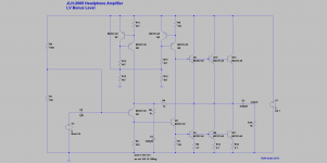
R18/C5 low-pass filters the PS noise and provides clean -2.3V relative to top rail for the CCS bias.
The other alternative is to replace your original 4k75 with a E102 CRD, though voltage headroom is perhaps a bit low.
So probably resistors & cap is a better solution, unless you struggle for space.
Patrick
The other alternative is to replace your original 4k75 with a E102 CRD, though voltage headroom is perhaps a bit low.
So probably resistors & cap is a better solution, unless you struggle for space.
Patrick
Last edited:
I was to add ventilation holes on top, but I think I have found a more elegant solution; I have added little spacers between the backplate and the cabinet. Therewith a gap of 2 mm is created. Now there is a nice area were natural convection can take place. Of course, adding ventilation holes on top would be better, but from the other hand, this way does not interfere much with the aesthetics (do not really like all those holes in the cabinet). More importantly, now the TIP41c's do not exceed 50 degrees C. Even when the amp is working for 6 hours! Pretty statisfied with the result. Proceed to the next project Mr. Kaplaars! Maybe the complementary version? Who is offering PCB's ? I´ve just bought the an Objective 2 PCB by the way. Very interested in how that PCB compares to this amp.
Ventilation gap:
? I´ve just bought the an Objective 2 PCB by the way. Very interested in how that PCB compares to this amp.Ventilation gap:
An externally hosted image should be here but it was not working when we last tested it.
.JPG)
Member
Joined 2009
Paid Member
A 2mm gap directly next to an AC Mains socket is only possible for DIY.
But whatever makes you happy.
BTW I like those cute handles at the back, even though not too functional for adult fingers.
You can build the complementary version by P2P on a vero board, similar to the F5-HA.
http://www.diyaudio.com/forums/pass-labs/271926-f5-headamp.html
No need for a PCB.
Patrick
But whatever makes you happy.
BTW I like those cute handles at the back, even though not too functional for adult fingers.
You can build the complementary version by P2P on a vero board, similar to the F5-HA.
http://www.diyaudio.com/forums/pass-labs/271926-f5-headamp.html
No need for a PCB.
Patrick
I knew someone would comment on that Of course the IEC mains socket pins inside are well insulated with heat shrink. You can't reach them with your fingers, since the connections are in the middle of the panel (leaving a gap of 1.5 cm). Even when some one thinks it is sane to put some wire through the ventilation holes, no short circuit can be made because of insulation .
Thank you! Of course those rack handles are just for aesthetics, my fingers are way too thick.
Interesting! That is indeed a nice simple circuit, perfectly suitable for vero board. Well, let's first finish the O2, but I would certainly like to try your circuit next.
Keep up the good work!
Regards Michael
Of course the IEC mains socket pins inside are well insulated with heat shrink. You can't reach them with your fingers, since the connections are in the middle of the panel (leaving a gap of 1.5 cm). Even when some one thinks it is sane to put some wire through the ventilation holes, no short circuit can be made because of insulation . Thank you! Of course those rack handles are just for aesthetics, my fingers are way too thick
. Interesting! That is indeed a nice simple circuit, perfectly suitable for vero board
. Well, let's first finish the O2, but I would certainly like to try your circuit next.Keep up the good work!
Regards Michael
I was referring to the JLH complementary headphone amplifier circuit, nit the F5-HA Mosfet amp :
http://www.diyaudio.com/forums/pass-labs/271926-f5-headamp-3.html#post4336111
The Class-A Amplifier Site - JLH Headphone Amplifiers (Circuit 2)
After all, this is the JLH headphone Amp thread.
Patrick
http://www.diyaudio.com/forums/pass-labs/271926-f5-headamp-3.html#post4336111
The Class-A Amplifier Site - JLH Headphone Amplifiers (Circuit 2)
After all, this is the JLH headphone Amp thread.
Patrick
- Home
- Amplifiers
- Headphone Systems
- JLH Headphone Amp