100 mV is far too much for sensitive, low resisitance iem
for some that level of AC would drive them to >110 dB SPL - will certainly push the coils far off center, increase distortion
But this is not AC, it is DC. It dissipates 0,3 mW on 32 ohm phones. Phones can accept 200..2000 mW electrical power, and >90% of it will be converted into heat. So 100 mV DC does not damage phones.
")
But I cannot say anything about distortion caused by little constant membrane displacement from center position by DC offset... Somebody measured it?
Last edited:
Hello All
Thank you all for your kind comments...
I wonder if anyone is still interested in making the JLH Headphone amp ???
Miles
Hi.
Yes. Thank you. Very informative.
Weak bass compared to what? And with what kind of headphones?
The JLH as suggested has an output impedance of 2.2 ohms, it should sound like a good portable player or somesuch. A typical integrated amp's headphone jack with its much higher output impedance gives a somewhat to considerably "fatter" sound with many cans.
Other than that, the places I would look in case of a real problem (RMAA loopback measurement may identify it) are C4 (the electrolytic in the feedback) and C1 (the input coupling cap). I would not connect an issue with low bass to the choice of output transistors. The amp should play fairly happily with bog standard TIP31A/B/Cs.
.....I experienced this amp has weak bass.....
Something must be wrong with your components. I've built this and it has very good bass. It's a very good sounding amp. My output stage was BD139. Worth the trouble building one !
About output offset. I get only a couple of mV. While 100mV might not damage the voice coil of the phones it will displace it quite a bit and cause distortion and also limited excursion in one direction if not anything else. Obviously maximum clean bass response will be reduced. Why do you get so much offset ?
About output offset. I get only a couple of mV.
I could get a couple of mV from mine, but only after it had been running for an hour and was nice and toasty. On cold start it was easily over 100mv.
Cant say i had any complaints about bass response, overall i was very impressed with mine. Having said that if you bought one of the Chinese kits from eBay the components provided are, well, utter garbage which may be part of your problem. The more bits i replaced on mine the better it got, but i eventually got bored with it and cannibalized it for the parts.
If the heat sink runs very hot, you are running too much bias and/or the heat sinks are too small. I ran mine at much lower output stage bias currents too and it still sounds very good ! Worth it putting it into a box and using it !
I plan to add a relay cut out to prevent dc mishaps. For those who do not want relays or ANY dc problems, you could use the single supply version with a capacitor at the output. That sounds very good too. There is a slight difference in how the LF sounds. I thought the split supply goes just a tad deeper and was tighter bass(?) . But if you didn't compare you wouldn't miss anything. Sounds very good too !
100mV start and dropping to a few millivolts is OK but not acceptable as you can do better than that nowadays.
Something must be wrong with your components. I've built this and it has very good bass. It's a very good sounding amp. My output stage was BD139. Worth the trouble building one !
?
I built several amp (approx. 30 different type ones) and JLH has weak bass for my ears. I bought components in a local store in Hungary, BC327/337-40 and TIP41C. My friend build this amp with original parts from eBay KIT and it's bass was similar.
I experienced on many amps that power transistor can effect the bass response significantly. Eg. MJE243/253 has warmer sound than BD139/140.
So change power BJT in JLH was only an idea...
Hi,
as of today I am also a proud owner of one JHL from fleabay, thanks to this wonderful thread!
A quick workover (insert feedback cap in right direction, change 0 ohm resistors to proper wire links), and I fired the thing up. Everything seems ok, dc offset after some warm up can be (practically) nulled out. However, upon turn-off, DC offset jumps to about 1.8V amd drops sloooowly to 0V (while discharging reservoir caps?). Has anybody experienced the same behaviour?
Best regards,
hallodeletue
You sholu use C=0.02/R caps, where C is in [F] and R is in [ohm] (R is the total load). And use 100 ohm fix resistor at the output for discharge caps. Caps could not discharge without a load resistor or headphone.
The discharge time is t=2*R*C (in SI units), where R is the total load.
The total load:
R=Res*Z/(Res+Z), where Res is resistor resistance and Z is the headphone impedance. If you use high impedance phones, you can use Res=1 kohms instead of 100 ohms.
The discharge time is t=2*R*C (in SI units), where R is the total load.
The total load:
R=Res*Z/(Res+Z), where Res is resistor resistance and Z is the headphone impedance. If you use high impedance phones, you can use Res=1 kohms instead of 100 ohms.
Last edited:
Hi guys! I would like to thank you all for the interesting posts that were added in this thread. I have bought the same PCB and implemented some of the modifications that have been described. However one problem remained; indeed there is major fluctuation in DC offset (temperature induced) and it is very difficult to keep it stable. But I've found a solution! I've modified the circuit by adding a DC servo circuit. Now it is very stable, it performs more relieable and it actually sounds pretty decent.
Pre-modification:
Modified board:
Here is some more info + schematics:
"JHL" headphone amp | Rock Grotto
Pre-modification:
An externally hosted image should be here but it was not working when we last tested it.
Modified board:
An externally hosted image should be here but it was not working when we last tested it.
Here is some more info + schematics:
"JHL" headphone amp | Rock Grotto
Last edited:
I'm not really too enamored with this circuit, but one neat trick is how it works at 5 V single supply (USB, every little charger on the planet etc.). As a cute, dirt cheap little headphone amp for IEMs, maybe it has some merit...
Attachments
I've tested the circuit for a while and it keeps performing like it should. I believe we can safely assume that, with the modification, the amp is OK . Made some progress today with the cabinet:
. Made some progress today with the cabinet:An externally hosted image should be here but it was not working when we last tested it.
I have just finished my JHL headamp By the way, I forgot to mention something. Before I soldered the TIP41c's that are included in this kit, I have checked if they were okay. They had a beta that was not according to factory specifications (probably fakes, the logo was not correct either). Therefore I have bought new trannies (replaced the SO-92's as well) from a relieable source, and threw the shipped parts into the bin. I addition I have changed the volume potentiometer to an original ALPS. It all adds up to a more reliable and sonically improved headamp. I am actually pretty statisfied with how it performs. There is no offset, and no noiticable hum or static noise detectable.
And off course some pictures of the finished product:
By the way, I forgot to mention something. Before I soldered the TIP41c's that are included in this kit, I have checked if they were okay. They had a beta that was not according to factory specifications (probably fakes, the logo was not correct either). Therefore I have bought new trannies (replaced the SO-92's as well) from a relieable source, and threw the shipped parts into the bin. I addition I have changed the volume potentiometer to an original ALPS. It all adds up to a more reliable and sonically improved headamp. I am actually pretty statisfied with how it performs. There is no offset, and no noiticable hum or static noise detectable.And off course some pictures of the finished product:
An externally hosted image should be here but it was not working when we last tested it.
.JPG)
An externally hosted image should be here but it was not working when we last tested it.
.JPG)
An externally hosted image should be here but it was not working when we last tested it.
.JPG)
I'm not really too enamored with this circuit, but one neat trick is how it works at 5 V single supply (USB, every little charger on the planet etc.). As a cute, dirt cheap little headphone amp for IEMs, maybe it has some merit...
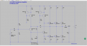
Noise from the power supply is easily introduced through R8 to the base of Q4. That noise needs to be filtered.
R10 and R12 must be partitioned to insert a filter capacitor from that point to + 5 V. For example, two 2K2 resistors in series with a small 47 uF capacitor from the junction of these resistors to + 5 V. This helps greatly to reduce the noise introduced by the power supply to the path of the audio signal.
R2, R13 and R15 have no function in this circuit.
Q4 must be a BC560C instead of BC327-40. Q3 must be a BC550C instead of BC337-40.
The gain required is only 2 or 6 dB?.
regards
- Home
- Amplifiers
- Headphone Systems
- JLH Headphone Amp