Are you going to build a portable or stationary amp? If you're going for the latter you could use LT1028 with some kind of buffer. There are many buffers to choose from. Either a discrete diamond buffer (look at eg PPA v2 or LISAIII), complementary MOSFET like M3, single end class A like Tori amp, monolithic buffer like PIMETA etc. Do some reading at tangentsoft.net and amb.org
If you use LT1028 be sure to compensate it properly. I've found that it overshoots and even oscillates without proper compensation at "normal" gain (for headphone use). http://www.diyaudio.com/forums/chip...-audio-integrated-opamps-123.html#post2028124 The first waveform is without input cap and compensation cap.
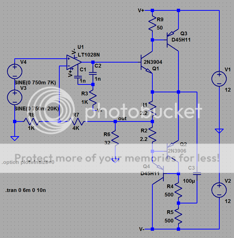
The picture below is the curciut from the example in the link.
If you use LT1028 be sure to compensate it properly. I've found that it overshoots and even oscillates without proper compensation at "normal" gain (for headphone use). http://www.diyaudio.com/forums/chip...-audio-integrated-opamps-123.html#post2028124 The first waveform is without input cap and compensation cap.
The picture below is the curciut from the example in the link.
Attachments
you probably should also plan on using the datasheet "overcompensation" (page 8 graphs - not shown in example circuits) using pin 5
with the local feedback C shown in Nelson's schematic the LT1028 is running unity gain at high frequencies and it is not unity gain stable wihtout using the overcompensation C between pin 5 and the output - may require several hundred pF
also the headfi fashion for jfet ccs bias is not the best for these circuits if you want to swing close to the power supply V
Might be a hint that the Grado amp uses a much higher power op-amp. Not as clean as some others, but higher power. About 50 mW where the best we can do with a good amp is about 35. The National buffer follower looks like a good solution. It can drive half a watt! Of course, arguments if it should be inside or outside the feedback loop.
If you have high Z cans, in other words not Grado's, then you have more options like the MCoy as it is. BTW, You can get a Grado clone off the auction for $35. Board, caps, resistors, and Alps pot. As it comes with the higher power op-amp, you are OK as is, or just swap in the op-amp of your pleasure and check compensation. I bought some to use as generic preamps. Cheaper than I can build.
If you have high Z cans, in other words not Grado's, then you have more options like the MCoy as it is. BTW, You can get a Grado clone off the auction for $35. Board, caps, resistors, and Alps pot. As it comes with the higher power op-amp, you are OK as is, or just swap in the op-amp of your pleasure and check compensation. I bought some to use as generic preamps. Cheaper than I can build.
Aha, that's why it oscillated I guesswith the local feedback C shown in Nelson's schematic the LT1028 is running unity gain at high frequencies and it is not unity gain stable wihtout using the overcompensation C between pin 5 and the output - may require several hundred pF
")
The TLE2062 is FET input and has around 80 mA of output current, more than the 4556 in the Grado amp. It sounds very good too when it drives headphones.Might be a hint that the Grado amp uses a much higher power op-amp. Not as clean as some others, but higher power.
No, it didn't oscillate with the compensation shown above. It oscillated without compensation. The bottom square wave is with the compensation above. I think it's close to perfect.Aha, that's why it oscillated I guess
I've tried capacitors from output to pin 5. It doesn't make the amp more stable, produce a better looking square wave or sound any better.
but will you always be lucky?
I've used the LT1028 professionally in strain gage amps with a gain -1 bridge balance circuit and 50' cables - the over compensation cap does improve stability into the heavy capacitive load
the LT designers/apps writers are really the best in the business - its worth paying attention to their description of the chip as not unity gain stable
OK, notice taken. Thank you for the advice. I didn't use more than 100 pF between the over-comp pin and output. That was the largest value I had at hand. When looking in the data sheet and running some spice sim, I can see that I should've tried something like 1 or 2 nF. I'll try it some time to give this opamp a second chance.I've used the LT1028 professionally in strain gage amps with a gain -1 bridge balance circuit and 50' cables - the over compensation cap does improve stability into the heavy capacitive load
the LT designers/apps writers are really the best in the business - its worth paying attention to their description of the chip as not unity gain stable
The comp caps and input resistor was choosen by trial and error. I have sockets for the resistors and capacitors.
This opamp really needs some attention to work properly. Not a drop in replacement. It's the same with AD797.
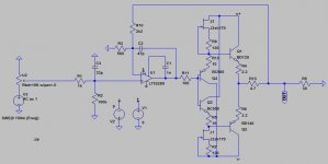
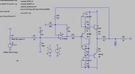
not talking CMOY here anymore but using broadly similar discrete buffer components I'd look at something like this:
Q1,3 cfp has similar current gain but lower distortion than the complemetary Darlington/"Diamond" output
Q2,4 is a feedback ccs with a twist - tapping the current sense resistor R1,2 in the middle gives push-pull Class A output, ~170mA quiescent - >300mA pk output but does give hard current limit at 2x quiescent
the LT1028 comp pin overcompensation is used with a 2-pole network to get some more of the LT1028's high open loop gain working in the global loop at audio frequencies while still cutting/compensating high frequency gain to hopeully provide robust stability with the buffer in the loop - probably should use smt C1,2 to keep parasitic inductance down
note that feedback R is too high to really take advantage of LT1028 low noise, would also have a problem with practical input volume pot values - the input current noise of the LT1028 wipes out any advantage from the 1nV voltage noise with KOhm impedance on either input
the sim shows distortion componenets < -120 dB at audio frequencies
Attachments
Last edited:
Hi,
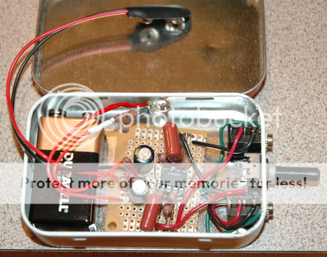
I've a problem/question about a Cmoy I built following the tangentsoft.net site.
I noticed two issues: one is noise and one is required Voltage.
First of all there is lot's of humming/noise when I power it using a switcher wall-wart 24V, if I use a 12V linear wall-wart (heavy one..) the hiss is a lot less disturbing (almost acceptable but still hearable).
The problem is that if I use the 24V switcher the Cmoy runs for about a couple of minutes at half volume and then shuts almost down (the volume automatically drops). What can this be?
Since with the linear 12V trafo the operating time is around 30secs before "shutting down", I was presuming the Voltage is insufficient but the specs of my chip are stating 30V are anyway the max (and wouldn't 12V suffice anyway??). I do use an LM49860.
What else could it be? The chip is not getting hot in any way, the voltage I measured across it's pins seem ok and I could not see any DC voltage on the output jack.. so no other clue..
Additionally I also noticed that touching the volume pot handle (metal) the humm/noise lowers a lot (like one half of humm, making it dead silent when using the 12V linear trafo). I also checked to have put the vol pot to ground and it seems so.. maybe is there something not ok there?
Kr,
tent:wq
I've a problem/question about a Cmoy I built following the tangentsoft.net site.
I noticed two issues: one is noise and one is required Voltage.
First of all there is lot's of humming/noise when I power it using a switcher wall-wart 24V, if I use a 12V linear wall-wart (heavy one..
) the hiss is a lot less disturbing (almost acceptable but still hearable).The problem is that if I use the 24V switcher the Cmoy runs for about a couple of minutes at half volume and then shuts almost down (the volume automatically drops). What can this be?
Since with the linear 12V trafo the operating time is around 30secs before "shutting down", I was presuming the Voltage is insufficient but the specs of my chip are stating 30V are anyway the max (and wouldn't 12V suffice anyway??). I do use an LM49860.
What else could it be? The chip is not getting hot in any way, the voltage I measured across it's pins seem ok and I could not see any DC voltage on the output jack.. so no other clue..
Additionally I also noticed that touching the volume pot handle (metal) the humm/noise lowers a lot (like one half of humm, making it dead silent when using the 12V linear trafo). I also checked to have put the vol pot to ground and it seems so.. maybe is there something not ok there?
Kr,
tent:wq
Well I understood you can use several different op-amps with it and that the LM49860 or LM4562 should give good reults too, or am I wrong? The LM49860 should be even better from the specs.. It is indeed working, at least for some second..
Am I maybe having a wrong pinout and didn't notice it (I double checked both dataspecs and the pinout seems the same, also the Voltage supported seems so wide on both, that my 12V should definitely suffice)?
What is introducing this sort of "protection" after some second and the PSU being not the cause?
tent:wq
The CMOY headphone amp on Tangentsoft is designed for the opamp OPA2132.
Why are you using LM49860?
should look like this:
Last edited:
Hi Tent,
I would recommend building the CMOY following Tangent's directions exactly.
Use a 9V battery for the power supply and an OPA2132 for the opamp.
Keep it simple! Introducing wal-warts with different and unknown output voltages
only adds more variables when it comes time to troubleshoot the circuit.
You must use the most care when it comes time to wire up your inputs, outputs
and volume control. Be sure you are making the proper connections! Be sure your
solder connections are good and not touching other parts or traces.
Use a DIP-8 IC socket. That way you don't have to worry about over heating the
op-amp if your soldering skills aren't perfect. Plus it will allow you to try other
op-amps, once you know the circuit is working.
...by no way am i an expert in electronics! but i have built this headphone amp per
Tangent's instructions - and it worked! Provide some pictures of your work so far,
they can help a lot in troubleshooting.
LM4562 is a little bit pickier than OPA2132 - power supply decoupling becomes important. It has plenty of output current capacity, though, and should be able to drive headphones (with an impedance > 60ish ohms) fairly well. (You might have some trouble with high volumes and 32 ohm headphones).
I've not personally tried it in a cmoy, though, only in preamps delivering into much higher impedances.
I've not personally tried it in a cmoy, though, only in preamps delivering into much higher impedances.
Last edited:
Hi Seekerr,
so you mean that LM4562 and LM49860 are much more prone to receive noise from PSU, so I've to work more on the decoupling? Ok what can I do? Maybe I'm going to put some snubber caps under the two PSU caps (I'll try 270uF||1uF||0.1uF) and try to stick to the linear 12V trafo.
The headphones I use are from Sony with 40ohms. Is that about headphones impedance also about noise and humm or about the "protection"?
Indeed, what about the strange "protection" coming in after some seconds of usage?
I tried to put a LM4562 I had on hand instead of the LM49860 and the things got much more worse, now after just some 5seconds playback the "protection" kicks in! What could that be? Unluckily I have no OPA2132 on hand to test..
tent:wq
I'll be honest, I've never managed to push any opamp into input-overvoltage or output-overcurrent protection, so I don't know what the symptoms of that are. But your problem sounds weird, and I think it's worth trying OPA2132 just because it's a very tolerant opamp - if even that won't work, something in your circuit is very wrong. Try powering your circuit from two 9V batteries - perhaps it's actually your power supply which has issues.
The deal with low impedance headphones is to do with output current capacity and ohms law. For more volume, you've got to swing more voltage, and for a given impedance, current scales with voltage in a fixed ratio - that is, Current = Voltage / Impedance.
Low impedance headphones need less voltage to reach a given volume, but demand a lot of current, relatively speaking. A 40 ohm headphone is a relatively difficult load for a lot of opamps.
For decoupling, the standard recommendation is an 0.1uF ceramic from each opamp power pin to ground - as close to the opamp as possible.
- Status
- This old topic is closed. If you want to reopen this topic, contact a moderator using the "Report Post" button.
- Home
- Amplifiers
- Headphone Systems
- Cmoy headphone amp?