Improvments to "Tube Headphone Amplifier/Preamp with Relay-Based Input and Power Swi"
Hello I have been building a valve headphone amplifier based on:
http://headwize.com/projects/showfile.php?file=ahammer1_prj.htm
It's been quite a long build due to inexperience with valve circuit construction techniques. For example I initially put boards on the bottom of the case and valve bases into the lid, but then how was I to connect the amplifier to the power supplies .
.
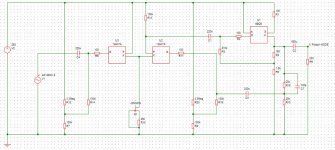
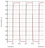
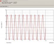
I decided to run some simulations of the circuit. I was slightly disappointed to discover a THD of 1.53% using the original circuit to drive a 150ohm load 1vpp 1khz sine. Also the 20dB gain of the original circuit was too high. I reasoned to introduce some global negative feedback and the results appear promising, with the same output I get 0.024% THD. Also Square waves are not ringing even when driving a 100nF capacitor.
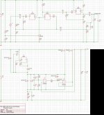
During my exams I also developed an improved power supply for this project. The improved power supply is a cascoded floating regulator that at least in simulation had very good performance. However as I ran the simulations a few months ago I can't quite recall how I got them to converge
The large cap at the output (100uF) is to ensure stability, I found the circuit would oscillate if there was not >40uF at the output. Not quite sure how to ensure stability properly as I currently only have familiarity with the barkhousan citation however this gets quite cumbersome trying to figure out where all the parasitics are!
I have enclosed schematics of both circuits and would like to solicit suggestions for further improvements!
Hello I have been building a valve headphone amplifier based on:
http://headwize.com/projects/showfile.php?file=ahammer1_prj.htm
It's been quite a long build due to inexperience with valve circuit construction techniques. For example I initially put boards on the bottom of the case and valve bases into the lid, but then how was I to connect the amplifier to the power supplies
.I decided to run some simulations of the circuit. I was slightly disappointed to discover a THD of 1.53% using the original circuit to drive a 150ohm load 1vpp 1khz sine. Also the 20dB gain of the original circuit was too high. I reasoned to introduce some global negative feedback and the results appear promising, with the same output I get 0.024% THD. Also Square waves are not ringing even when driving a 100nF capacitor.
During my exams I also developed an improved power supply for this project. The improved power supply is a cascoded floating regulator that at least in simulation had very good performance. However as I ran the simulations a few months ago I can't quite recall how I got them to converge
The large cap at the output (100uF) is to ensure stability, I found the circuit would oscillate if there was not >40uF at the output. Not quite sure how to ensure stability properly as I currently only have familiarity with the barkhousan citation however this gets quite cumbersome trying to figure out where all the parasitics are!
I have enclosed schematics of both circuits and would like to solicit suggestions for further improvements!
Attachments
Can now manage 20Vpp into 330ohm with 0.2% THD. Pleanty of headroom! could even drive some very efficiant speakers through a transformer with that. Into the worst case 60ohm 100nF it only manages 4.4vpp but still more than listening volume for grados etc. Anyway I'm going to build this over the next few days and will report back, should rearly get a signal generator as mine is very tempremental.
Quite like valves as output devices, shame about the need for heater supplies pushing the cost up. Can't seem to find cheap transformers in the uk with heater windings so end up getting a seperate transformer for the heaters.
Quite like valves as output devices, shame about the need for heater supplies pushing the cost up. Can't seem to find cheap transformers in the uk with heater windings so end up getting a seperate transformer for the heaters.
Attachments
- Status
- This old topic is closed. If you want to reopen this topic, contact a moderator using the "Report Post" button.