Just built a nice headphone amp but last night I saw one of JB's designs with positive and negative rails. Interesting design. How do this work? Is he allowing an output without big caps? It shows to outputs and I'm trying to work out the signal path here.
I'm currently using big electrolytics on the output to drive the headphones. Would be great to have a pure OTL without any caps like this one.
Has anyone built one of these? What do they sound like?
How would you build the power supply for this? Does anyone have schematics?
Or if there is a thread related to this design please advise.
many thanks
Attachments
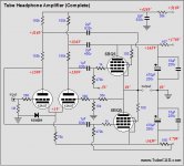
Yes the bipolar supply allows the elimination of the output cap. It's really just the same as how most SS amps are built. Headphones are high enough impedance to more easily be driven OTL. Did the article say if this was to drive 32 ohm headphones or 600 ohms? Note that if you built it you would have to fiddle with resistors to get DC on the output close to zero. It looks like JB has done this with the 167 and 156 ohm resistors on the rails. That's just for the simulation though, you would have to play with these values or use a high wattage pot. My personal preference is fixed resistors.
The tubes are strapped as triodes, so it is not a pentode amp.
I don't see two outputs. Do you mean the ground connection?
The tubes are strapped as triodes, so it is not a pentode amp.
I don't see two outputs. Do you mean the ground connection?
I don't care how clever your design is, or how good it sounds, if I am strapping something to my head and it involves voltages above about 24V, there needs to be, at a minimum, a cap between me and it. Maybe there's an exception for well made and reputable electrostatics, but maybe not.
dsavitsk said:I don't care how clever your design is, or how good it sounds, if I am strapping something to my head and it involves voltages above about 24V, there needs to be, at a minimum, a cap between me and it. Maybe there's an exception for well made and reputable electrostatics, but maybe not.
+1
One thing I'd like to add about the Broskie circuits. A lot of people think he's a genius, and he definitely seems to know his stuff. However, as a learning experience I have tried many of his circuits in simulation, and sadly, many of them did not work exactly as shown. They may work in reality, but this is something that you may want to keep in mind. Just to be clear, I'm not talking about the circuits for which he has pcbs/kits for sale, but those in which he explores ideas. The circuit you're considering may be one of them?
Just my 2c.
I have tried many of his circuits in simulation, and sadly, many of them did not work exactly as shown.
I built this regulator.
http://www.glass-ware.com/tubecircuits/High_Voltage_Regulator.html]Broskie regulator[/URL]
It didn't work... at least I couldn't make it work.
Cheers.
rman said:
I built this regulator.
http://www.glass-ware.com/tubecircuits/High_Voltage_Regulator.html]Broskie regulator[/URL]
It didn't work... at least I couldn't make it work.
Cheers.
OT: give this a try if you want something good that works. Plus, salas is around and is very helpful. In spite of its "simplistic" name, it can run circles around some "super" regulators.
OT: give this a try if you want something good that works. Plus, salas is around and is very helpful. In spite of its "simplistic" name, it can run circles around some "super" regulators.
I definitely second that. My HV shunt has 100+ hours on it, works perfectly and sounds better than any psu I had so far... (headphones amps only...;-))
ikoflexer said:
One thing I'd like to add about the Broskie circuits. A lot of people think he's a genius, and he definitely seems to know his stuff. However, as a learning experience I have tried many of his circuits in simulation, and sadly, many of them did not work exactly as shown . . . . Just my 2c.
My experience too. I was interested in his Partial Feedback article but sims of it using LTspice didn't work. I came to the conclusion that it was theoretical and he hadn't tried it for himself.
rman said:
I built this regulator.
http://www.glass-ware.com/tubecircuits/High_Voltage_Regulator.html Broskie regulator
It didn't work... at least I couldn't make it work.
Cheers.
I know at least one man who could make it work, see:
http://gboers.xs4all.nl/daisy/home/g3/139/settravels/powersupply.html
http://gboers.xs4all.nl/daisy/home/g3/139/g1/monoblocks/highvoltagepsu.html
Here is his main site:
http://gboers.xs4all.nl/daisy/home/135.html
a very infomative site that I like very much
Cheer
Hi ncc.
From the page of your second link:
Maybe that was my problem when trying to test it!
I still have this thing laying around, should check it over and try again.
Cheers.
From the page of your second link:
There is a 1µF capacitor connected across the load resistors, I found that with a purely resistive load the regulator will not 'power up'.
Maybe that was my problem when trying to test it!
I still have this thing laying around, should check it over and try again.
Cheers.
rman said:After rechecking the board I found a missing connection after about a minute. Months ago when I built it, I couldn't find the flaw.It regulates voltage alright. will have a look with the scope tomorrow.
Hi rman,
Nice to hear that you've found the error
")
This regulator use a floating power supply for the reference voltage and error amplifier, I've experimented with this regulator by using a RC filter then a regulator (a LT3080) for the floating power supply, after that, high voltage output of the regulator is much cleaner than the original design.
Cheer
hi ncc.
Great idea! Regulating the op amps supply makes a lot of sense to me as most op amp supplies are regulated.
Well, I had a look at the output and it is oscillating quite nicely at about 3 MHz, 0.3v pp. I put in a larger gate stopper (1k) as close to the gate as I could get. This only distorted the 3 MHz waveform.
The load for this test is a big wire wound pot set to 12.5k (20ma. @250v). It was intended for a phonostage, the regulator that is. Interestingly, when the load is adjusted to about 12.1k, the oscillation stops. The Mosfet is an IRF BC40 (found on shop floor at work). swapped in an IRF 540 and the amplitude of the oscillation rises. I really don't' know enough to account for all this. I can only conclude that layout is critical, and that mine is not great.
I guess we have hijacked this thread as the original topic seems to have disappeared.
- Status
- This old topic is closed. If you want to reopen this topic, contact a moderator using the "Report Post" button.
- Home
- Amplifiers
- Headphone Systems
- John Broskie's headphone design using pentodes