I heard so much about directly heated triodes that I finally decided to build a DHT based headphone amp. There are not that many schematics for such a thing out there, especially for my requirements:
* low cost; most output transformers are quite expensive, so I'd like to avoid them if possible
* relatively simple to build
* not use exotic tubes
* not use dual rail psu for mosfet (or maybe, just to get rid of the output cap)
* direct couple between DHT driver and output stage
I've been thinking that something like a 3a5, or some other DHT as the driver and a mosfet output stage could work, but have no idea if it's a disaster or not, I have no experience with such things. Should I just save for some output transformer and have a 71a output stage?
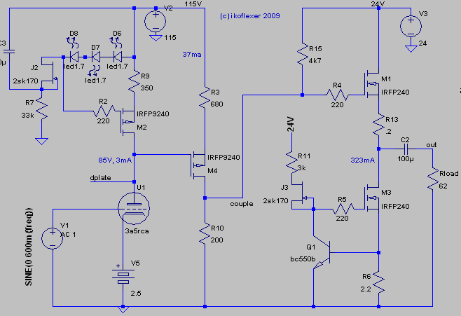
For now, here's a rough sketch. The topology is simple enough, tube driver with ccs load, directly coupled to a mosfet output stage with a current sink below it.
In any case, what do you guys think of this circuit, anything that outright stinks?
(I loath that 100uF C2. How can I get rid of it?)
* low cost; most output transformers are quite expensive, so I'd like to avoid them if possible
* relatively simple to build
* not use exotic tubes
* not use dual rail psu for mosfet (or maybe, just to get rid of the output cap)
* direct couple between DHT driver and output stage
I've been thinking that something like a 3a5, or some other DHT as the driver and a mosfet output stage could work, but have no idea if it's a disaster or not, I have no experience with such things. Should I just save for some output transformer and have a 71a output stage?
For now, here's a rough sketch. The topology is simple enough, tube driver with ccs load, directly coupled to a mosfet output stage with a current sink below it.
In any case, what do you guys think of this circuit, anything that outright stinks?
(I loath that 100uF C2. How can I get rid of it?)
Code:
Harmonic	Frequency	 Fourier 	Normalized	 Phase  	Normalized
 Number 	  [Hz]   	Component	 Component	[degree]	Phase [deg]
    1   	1.000e+03	2.416e+00	1.000e+00	    0.41°	    0.00°
    2   	2.000e+03	1.758e-03	7.276e-04	  -45.57°	  -45.98°
    3   	3.000e+03	3.010e-04	1.246e-04	   57.20°	   56.80°
    4   	4.000e+03	4.995e-05	2.068e-05	  159.87°	  159.46°
    5   	5.000e+03	9.582e-06	3.966e-06	 -113.65°	 -114.06°
    6   	6.000e+03	3.279e-06	1.357e-06	  -62.77°	  -63.18°
    7   	7.000e+03	2.551e-06	1.056e-06	  126.37°	  125.96°
    8   	8.000e+03	2.099e-06	8.687e-07	  -20.93°	  -21.33°
    9   	9.000e+03	3.580e-06	1.482e-06	  -91.21°	  -91.62°
Total Harmonic Distortion: 0.073845%Hello.
No big expert here but I believe that to drive a low impedance load like a pair of headphones, you either need an output transformer, or a big output capacitor. If I am wrong someone please correct me.
Cheers.
(I loath that 100uF C2. How can I get rid of it?)
No big expert here but I believe that to drive a low impedance load like a pair of headphones, you either need an output transformer, or a big output capacitor. If I am wrong someone please correct me.
Cheers.
Some quick observations:
A tube amplifier stage with a solid state follower output stage is a fine idea.
The so-called ‘magic’ of Directly Heated Triodes (in my opinion) is simply down to their linearity, so make sure you operate it in a linear section of it’s characteristics.
I am no expert in solid state ‘discrete’ circuits so will leave the analysis to others, however if I were on your path I would do it like this:
DHTriode voltage amp with CCS load
DC cathode (despite the theoretical limitation of voltage gradient across the cathode)
Capacitor coupled to next stage (yup, it’s simple and it works, and gets rid of your M4 FET)
Follower based on something simple such as Project 83 at ESP …http://sound.westhost.com/project83.htm (but with suitably adjusted power).
Don't worry too much about the output cap for now.
The gain requirement of the triode will be determined by the requirements of your ‘phones (impedance and sensitivity). In general head for quality not quantity. For most ‘phones a continuous 60-ish mW is more than enough, so if you can peak at 1/4 Watt then all is well.
: )
Gordy, thanks! In fact I came across this ESP bit some time ago and totally forgot about it in the meanwhile 
You know, I had tried the schematic above with RC coupling but got poor frequency response unless I used a large cap, hence the direct coupling. I might actually try both versions, with the mosfet, and with the cap (I just want to refrain from having to buy fancy caps).
As for headphones, I have the run of the mill Sony MDR-V6, claiming 106 dB/mW, 63 ohm at 1kHz. Lack of lots of power (read loud) is not something I worry too much about.
You say I shouldn't worry too much about the output cap, but considering its size, it would have to be an electrolytic. A couple of "better" output caps will probably run at prices similar to some output transformers. The all of a sudden a power triode + transformer output doesn't look so unappealing, considering that it does away with the extra psu needed for the mosfet output (just thinking aloud here).
rman, I was thinking perhaps a DC servo might work, as wavebourne has done (somewhere else on this forum).
Gordy said:Don't worry too much about the output cap for now.
bigwill said:IMO the coupling capacitor isn't a problem
The coupling cap is going to undo any goodness done by the DHT. It is the bottleneck of the amp.
Gordy said:The gain requirement of the triode will be determined by the requirements of your ‘phones (impedance and sensitivity). In general head for quality not quantity. For most ‘phones a continuous 60-ish mW is more than enough, so if you can peak at 1/4 Watt then all is well.
1/4 watt is way more than you'll likely need.
For using a DHT for low impedance phones, have a look here: http://www.ecp.cc/less-pressivo-plus-plus.html
astouffer said:You could always use a DHT for gain and a buffer chip like a BUF634 or HA-5002.
These chips really sound awful, and both need to be inside feedback loops of opamps or else they need output caps.
dsavitsk said:The coupling cap is going to undo any goodness done by the DHT. It is the bottleneck of the amp.
Pfff. A properly biased electrolytic sounds fine

ikoflexer said:
As for headphones, I have the run of the mill Sony MDR-V6, claiming 106 dB/mW, 63 ohm at 1kHz.
OK, then 8 mW will very likely be more than loud enough! Allow a bit above that for 'headroom'. Say 32 mW.
ikoflexer said:
The all of a sudden a power triode + transformer output doesn't look so unappealing, considering that it does away with the extra psu needed for the mosfet output (just thinking aloud here).
Volume control > 6H30 (run at about 25 mA from a CCS load, bias about -3V, about 80V on the anode) > small (about 3 microfarad) parallel-feed capacitor from anode > output transformer primary (with the other end of primary returned to ground).
For ac coupled o/p transformer see Sowter or Electra-Print (or possibly Hammond 119DA).
ikoflexer said:
rman, I was thinking perhaps a DC servo might work, as wavebourne has done (somewhere else on this forum).
...but if the servo fails you get hundreds of volts very close to your head?
: )
No need to be afraid of OPT's. Your power requirements are very low, and your phones are pretty high impedance. Edcor has SE transformers that start at around $20. At 10W they will only go to about 70Hz. But if you really only need 50mW or so, the LF extension will be much lower. You can even regap the transformer for more inductance, since your current will be low. You should easily be able to get 50mW output from a paralleled 3A5.
Sheldon
Sheldon
Alright, I'm back.
OK, I would not want to use an opamp. I think I should add that to the list of requirements.
Coupling cap; the general consensus seems to be that direct coupling is better, but yes, in my case there is an extra mosfet. I'll try again for a design with a coupling cap to have something to fall back on in case direct coupling would not work well.
dsavitsk, I've had a look at your site for some time now, nice! I have all the parts to build the mosfet version, and if it sucks I'll swallow the bitter pill and buy a couple of OTs. Yes, I had the Edcors in sight. Sowter and such, more money than I want to spend.
I should say that I built a 21LU8 based headphone amp (pentode part triode strapped), RC interstage coupling, power transformers re-purposed to OTs. Total cost not more than $50 and it sounds great. Now if I go to a cost of $100 for the DHT amp, it better be twice as good; or so I hope. You may laugh, but that's my personal challenge.
Gordy, the 6H30 has good rep, but I really want a DHT.
Sheldon, good tip about paralleling the 3a5. Didn't think about that. I have some other DHTs coming my way that I will consider for this project. Some 1j6g, 30, and even 71a.
Weird that from some comments I find on the web it seems so easy to build an excellent amp. Makes one wonder then why all those people over at headwize expend so much effort to get that special sound.
bigwill, what do you mean by a properly biased coupling cap? Sorry, I just don't understand what you meant by biasing in this context. Are you referring to the RC filter value?
Edit: typo
If you want to stay with the FET output, you might consider a simpler design. The 3a5 is a very linear tube. I think you'd do fine with a resistor load. Here's a simple output stage: http://www.tubecad.com/april_may2001/page13.html
The filament as a load wouldn't work with the DHT, but you can substitute a resistor there too. Without a transformer, the coupling cap that will influence the sound most is on the output. With that in place, I wouldn't add all the extra stuff to direct couple to the FET stage. You can use a good quality cap there at little expense.
You are going to have to have a good filament supply. I'd spend effort there. You will need a very quiet supply, constant current is a good choice. Search Rod Coleman's design. It looks complicated, but it's not if you break it down. Batteries are an option for a 3A5.
Sheldon
ikoflexer said:Alright, I'm back.
bigwill, what do you mean by a properly biased coupling cap? Sorry, I just don't understand what you meant by biasing in this context. Are you referring to the RC filter value?
Simply having a big enough DC voltage across the capacitor to accommodate the voltage swing
sheldon, interesting output stages over at tubecad. Ok, I've simplified the abomination somewhat. Have a look.
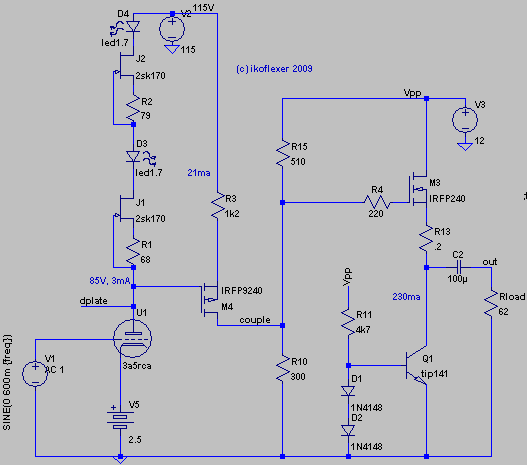
You will see the simple ccs load on the 3a5. I use double the jfets (if different Idss the source resistor needs to be adjusted offline until the voltage drop across the two jfets is roughly equal; the reason for this is that the 2sk170 has a 40V Vds max; I know it's a hack, but will look for more suitable jfet, with higher voltage).
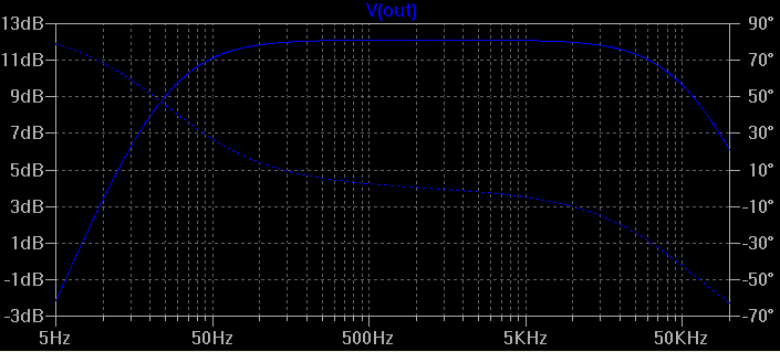
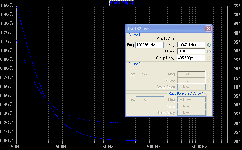
Funny, that simple ccs has this output impedance. Over 100kOhm at 1Mhz. Of course, in the real world it's not like that
So, the simpler circuit simulates a bit better for distortion. Nice figures for the voltage on the 3a5 plate (V(dplate)).
sheldon, using a suitable resistor to get the 3a5 in the same operating point simulates as seen below. I'm inclined to stay with the simple ccs. What do you think?
You will see the simple ccs load on the 3a5. I use double the jfets (if different Idss the source resistor needs to be adjusted offline until the voltage drop across the two jfets is roughly equal; the reason for this is that the 2sk170 has a 40V Vds max; I know it's a hack, but will look for more suitable jfet, with higher voltage).
Funny, that simple ccs has this output impedance. Over 100kOhm at 1Mhz. Of course, in the real world it's not like that
So, the simpler circuit simulates a bit better for distortion. Nice figures for the voltage on the 3a5 plate (V(dplate)).
Code:
Harmonic	Frequency	 Fourier 	Normalized	 Phase  	Normalized
 Number 	  [Hz]   	Component	 Component	[degree]	Phase [deg]
    1   	1.000e+03	1.335e+00	1.000e+00	    1.02°	    0.00°
    2   	2.000e+03	1.854e-04	1.389e-04	 -130.62°	 -131.64°
    3   	3.000e+03	2.844e-05	2.130e-05	   55.56°	   54.54°
    4   	4.000e+03	2.726e-06	2.042e-06	   11.59°	   10.57°
    5   	5.000e+03	4.017e-07	3.009e-07	  -94.13°	  -95.14°
    6   	6.000e+03	1.669e-07	1.250e-07	  105.29°	  104.28°
    7   	7.000e+03	1.916e-07	1.435e-07	   78.39°	   77.37°
    8   	8.000e+03	1.755e-07	1.315e-07	   73.31°	   72.30°
    9   	9.000e+03	1.813e-07	1.358e-07	   72.40°	   71.38°
Total Harmonic Distortion: 0.014049%


Fourier components of V(dplate)
DC component:85.6847

Harmonic	Frequency	 Fourier 	Normalized	 Phase  	Normalized
 Number 	  [Hz]   	Component	 Component	[degree]	Phase [deg]
    1   	1.000e+03	8.646e+00	1.000e+00	  179.64°	    0.00°
    2   	2.000e+03	8.206e-04	9.492e-05	   74.33°	 -105.31°
    3   	3.000e+03	6.109e-05	7.066e-06	 -140.98°	 -320.62°
    4   	4.000e+03	1.102e-06	1.275e-07	   22.94°	 -156.70°
    5   	5.000e+03	2.250e-06	2.602e-07	   93.33°	  -86.32°
    6   	6.000e+03	2.151e-06	2.488e-07	  111.49°	  -68.15°
    7   	7.000e+03	2.090e-06	2.417e-07	  143.39°	  -36.25°
    8   	8.000e+03	2.807e-06	3.246e-07	  123.89°	  -55.75°
    9   	9.000e+03	1.581e-06	1.828e-07	  113.01°	  -66.63°
Total Harmonic Distortion: 0.009518%


Fourier components of V(couple)
DC component:8.42537

Harmonic	Frequency	 Fourier 	Normalized	 Phase  	Normalized
 Number 	  [Hz]   	Component	 Component	[degree]	Phase [deg]
    1   	1.000e+03	1.360e+00	1.000e+00	   -0.41°	    0.00°
    2   	2.000e+03	1.504e-04	1.106e-04	 -123.51°	 -123.10°
    3   	3.000e+03	1.764e-05	1.297e-05	   52.67°	   53.08°
    4   	4.000e+03	1.318e-06	9.691e-07	    0.02°	    0.43°
    5   	5.000e+03	6.421e-07	4.721e-07	  -81.55°	  -81.14°
    6   	6.000e+03	3.784e-07	2.782e-07	  -74.86°	  -74.45°
    7   	7.000e+03	3.488e-07	2.565e-07	  -71.25°	  -70.84°
    8   	8.000e+03	3.301e-07	2.427e-07	  -75.17°	  -74.76°
    9   	9.000e+03	2.918e-07	2.145e-07	  -52.70°	  -52.28°
Total Harmonic Distortion: 0.011134%
sheldon, using a suitable resistor to get the 3a5 in the same operating point simulates as seen below. I'm inclined to stay with the simple ccs. What do you think?
Code:
Fourier components of V(out)
DC component:-8.26397e-008

Harmonic	Frequency	 Fourier 	Normalized	 Phase  	Normalized
 Number 	  [Hz]   	Component	 Component	[degree]	Phase [deg]
    1   	1.000e+03	6.720e-01	1.000e+00	    1.20°	    0.00°
    2   	2.000e+03	4.781e-03	7.115e-03	  -89.77°	  -90.97°
    3   	3.000e+03	1.080e-04	1.607e-04	    1.38°	    0.18°
    4   	4.000e+03	3.678e-06	5.473e-06	   85.54°	   84.35°
    5   	5.000e+03	2.154e-07	3.206e-07	 -123.01°	 -124.20°
    6   	6.000e+03	1.772e-07	2.637e-07	  -71.79°	  -72.99°
    7   	7.000e+03	1.748e-07	2.602e-07	  -68.22°	  -69.42°
    8   	8.000e+03	1.764e-07	2.625e-07	  -65.25°	  -66.45°
    9   	9.000e+03	1.775e-07	2.641e-07	  -61.29°	  -62.49°
Total Harmonic Distortion: 0.711664%


Fourier components of V(dplate)
DC component:85.7718

Harmonic	Frequency	 Fourier 	Normalized	 Phase  	Normalized
 Number 	  [Hz]   	Component	 Component	[degree]	Phase [deg]
    1   	1.000e+03	4.352e+00	1.000e+00	  179.83°	    0.00°
    2   	2.000e+03	3.092e-02	7.106e-03	   89.91°	  -89.91°
    3   	3.000e+03	6.925e-04	1.591e-04	  179.69°	   -0.14°
    4   	4.000e+03	2.173e-05	4.994e-06	  -93.44°	 -273.27°
    5   	5.000e+03	2.485e-06	5.711e-07	   63.45°	 -116.37°
    6   	6.000e+03	2.447e-06	5.624e-07	  105.75°	  -74.08°
    7   	7.000e+03	2.930e-06	6.734e-07	   97.13°	  -82.69°
    8   	8.000e+03	2.847e-06	6.543e-07	  105.15°	  -74.68°
    9   	9.000e+03	2.739e-06	6.295e-07	  113.49°	  -66.33°
Total Harmonic Distortion: 0.710828%


Fourier components of V(couple)
DC component:8.41166

Harmonic	Frequency	 Fourier 	Normalized	 Phase  	Normalized
 Number 	  [Hz]   	Component	 Component	[degree]	Phase [deg]
    1   	1.000e+03	6.845e-01	1.000e+00	   -0.23°	    0.00°
    2   	2.000e+03	4.865e-03	7.107e-03	  -90.34°	  -90.11°
    3   	3.000e+03	1.093e-04	1.597e-04	    0.16°	    0.39°
    4   	4.000e+03	3.562e-06	5.204e-06	   85.10°	   85.33°
    5   	5.000e+03	4.304e-07	6.288e-07	  -95.38°	  -95.15°
    6   	6.000e+03	4.220e-07	6.165e-07	  -76.21°	  -75.98°
    7   	7.000e+03	3.722e-07	5.438e-07	  -72.80°	  -72.57°
    8   	8.000e+03	4.392e-07	6.416e-07	  -62.21°	  -61.98°
    9   	9.000e+03	5.011e-07	7.320e-07	  -68.29°	  -68.06°
Total Harmonic Distortion: 0.710885%ikoflexer said:sheldon, interesting output stages over at tubecad. Ok, I've simplified the abomination somewhat. Have a look.
First, why not use a part for the CCS that is actually intended for this purpose and that will work better: DN2540 or IXYS 10M45. Both are depletion mode mosfets and both will work better here. Moreover, they are 400 and 450V parts.

Second, why are you using two mosfet followers? Why not just take the headphone out from the first one? So you'll need a bigger heatsink. But, you already have about 30mA through the first fet, so just bump it up a tad and save yourself a second mosfet, ps, ccs, etc.
dsavitsk said:
First, why not use a part for the CCS that is actually intended for this purpose and that will work better: DN2540 or IXYS 10M45. Both are depletion mode mosfets and both will work better here. Moreover, they are 400 and 450V parts.
Second, why are you using two mosfet followers? Why not just take the headphone out from the first one? So you'll need a bigger heatsink. But, you already have about 30mA through the first fet, so just bump it up a tad and save yourself a second mosfet, ps, ccs, etc.
Second suggestion I've tried initially, when I first looked at direct coupling, but couldn't get it working well. Didn't spend much time trying to fix it though, I'll revisit the issue. It'd be nice, of course, to get rid of using a whole lot of parts.
Regarding the DN2540 ccs; I've also tried that, but for some reason the simulated output impedance was not very good at all. I can give more details if interested.
- Status
- This old topic is closed. If you want to reopen this topic, contact a moderator using the "Report Post" button.
- Home
- Amplifiers
- Headphone Systems
- Class A, DHT driven, headphone amp