Hi Lars, the model, here it is.
.subckt 3a5plate P G K
CGP G P 3.2p
CGK G K 0.9p
CPK P K 1p
Bp P K I=((0.01225161666m)+(0.0002970483158m)*V(G,K))*uramp((14.07295141)*V(G,K)+V(P,K)+(-5.121091992))**1.5
.ends 3a5plate
It would be good if we were on the same page regarding the dn2540. I attached my sim file. If you could please try the fifth circuit there, and plot V(out5)/I(I5). That would be the simplest dn2540 ccs. Perhaps I'm making a mistake.
True about the ccs and psrr. But, I failed to mention this. I'm planning to use a very good (IMHO) discrete shunt regulator, something I've put a lot of effort into. A low voltage version of this regulator I've posted already in another thread (http://www.diyaudio.com/forums/showthread.php?postid=1859339#post1859339)
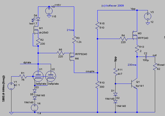
Now I have two circuits under consideration. Mosfet output stage:
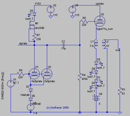
or 71a output stage (of sorts):
See guys, I do listen.
Not that I read too much into this, but let's consider. The mosfet output has a thd of about 0.025, most of it 2nd harmonic. The 71a output has a thd of about 0.3, much of it 2nd but a significant 3rd as well. In reality, as Sheldon said, the 71a might sound best, despite the numbers.
The model for the 71a that I used is from a datasheet:
.subckt type71a_cun P G K
CGP G P 7.4p
CGK G K 3.7p
CPK P K 2.1p
Bp P K I=((0.05906203251m)+(0.0003447315444m)*V(G,K))*uramp((2.73256969)*V(G,K)+V(P,K)+(-9.541876783))**1.5
.ends type71a_cun
.subckt 3a5plate P G K
CGP G P 3.2p
CGK G K 0.9p
CPK P K 1p
Bp P K I=((0.01225161666m)+(0.0002970483158m)*V(G,K))*uramp((14.07295141)*V(G,K)+V(P,K)+(-5.121091992))**1.5
.ends 3a5plate
It would be good if we were on the same page regarding the dn2540. I attached my sim file. If you could please try the fifth circuit there, and plot V(out5)/I(I5). That would be the simplest dn2540 ccs. Perhaps I'm making a mistake.
True about the ccs and psrr. But, I failed to mention this. I'm planning to use a very good (IMHO) discrete shunt regulator, something I've put a lot of effort into. A low voltage version of this regulator I've posted already in another thread (http://www.diyaudio.com/forums/showthread.php?postid=1859339#post1859339)
Now I have two circuits under consideration. Mosfet output stage:
or 71a output stage (of sorts):
See guys, I do listen.
Not that I read too much into this, but let's consider. The mosfet output has a thd of about 0.025, most of it 2nd harmonic. The 71a output has a thd of about 0.3, much of it 2nd but a significant 3rd as well. In reality, as Sheldon said, the 71a might sound best, despite the numbers.
The model for the 71a that I used is from a datasheet:
.subckt type71a_cun P G K
CGP G P 7.4p
CGK G K 3.7p
CPK P K 2.1p
Bp P K I=((0.05906203251m)+(0.0003447315444m)*V(G,K))*uramp((2.73256969)*V(G,K)+V(P,K)+(-9.541876783))**1.5
.ends type71a_cun
Attachments
While exploring this circuit, I came across something weird. How can the 2nd harmonic distortion be reduced after the mosfet stage? The 3rd goes up.
Check out the Normalized Component of V(out) vs. V(dplate).
Also, one more question. For type 71a, any sweet spot operating point?
Code:
Fourier components of V(out)
DC component:9.53347e-008

Harmonic	Frequency	 Fourier 	Normalized	 Phase  	Normalized
 Number 	  [Hz]   	Component	 Component	[degree]	Phase [deg]
    1   	1.000e+03	1.079e+00	1.000e+00	    1.17°	    0.00°
    2   	2.000e+03	2.867e-05	2.656e-05	   82.91°	   81.74°
    3   	3.000e+03	1.568e-05	1.453e-05	   13.70°	   12.53°
    4   	4.000e+03	1.194e-06	1.106e-06	   87.62°	   86.45°
    5   	5.000e+03	1.732e-07	1.605e-07	   95.73°	   94.55°
    6   	6.000e+03	1.864e-07	1.727e-07	   79.07°	   77.90°
    7   	7.000e+03	1.715e-07	1.589e-07	   59.37°	   58.19°
    8   	8.000e+03	1.931e-07	1.789e-07	   77.09°	   75.91°
    9   	9.000e+03	1.457e-07	1.349e-07	   67.41°	   66.24°
Total Harmonic Distortion: 0.003030%


Fourier components of V(dplate)
DC component:87.7156

Harmonic	Frequency	 Fourier 	Normalized	 Phase  	Normalized
 Number 	  [Hz]   	Component	 Component	[degree]	Phase [deg]
    1   	1.000e+03	8.758e+00	1.000e+00	  179.80°	    0.00°
    2   	2.000e+03	2.210e-03	2.524e-04	  -90.26°	 -270.06°
    3   	3.000e+03	1.970e-05	2.250e-06	  -39.87°	 -219.67°
    4   	4.000e+03	9.712e-07	1.109e-07	  110.58°	  -69.22°
    5   	5.000e+03	1.481e-06	1.691e-07	  111.53°	  -68.27°
    6   	6.000e+03	2.785e-07	3.180e-08	  118.17°	  -61.63°
    7   	7.000e+03	1.409e-06	1.609e-07	  127.46°	  -52.34°
    8   	8.000e+03	9.546e-07	1.090e-07	  172.07°	   -7.73°
    9   	9.000e+03	7.690e-07	8.780e-08	  129.67°	  -50.13°
Total Harmonic Distortion: 0.025240%


Fourier components of V(couple)
DC component:12.9908

Harmonic	Frequency	 Fourier 	Normalized	 Phase  	Normalized
 Number 	  [Hz]   	Component	 Component	[degree]	Phase [deg]
    1   	1.000e+03	1.101e+00	1.000e+00	   -0.26°	    0.00°
    2   	2.000e+03	2.734e-04	2.483e-04	   91.36°	   91.62°
    3   	3.000e+03	2.431e-06	2.208e-06	   65.17°	   65.42°
    4   	4.000e+03	2.515e-07	2.284e-07	   41.88°	   42.14°
    5   	5.000e+03	1.250e-07	1.135e-07	  -14.20°	  -13.94°
    6   	6.000e+03	1.869e-07	1.698e-07	  -58.91°	  -58.66°
    7   	7.000e+03	1.852e-07	1.682e-07	  -60.91°	  -60.66°
    8   	8.000e+03	1.043e-07	9.477e-08	  -44.52°	  -44.26°
    9   	9.000e+03	1.972e-07	1.791e-07	  -40.67°	  -40.42°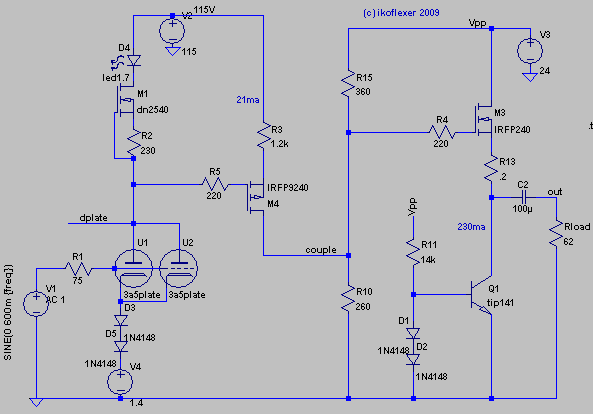
Total Harmonic Distortion: 0.024828%Onward we go. After some more this and that, the following seems more attractive than what I've explored so far. It is simpler for one, and I like that. The 3a5 is a pretty linear tube and I tried to find an operating point that's easy to set and shows some good numbers. Whether that will be so in reality, we'll see.
About 9dB gain and almost no phase shift in the audio frequency. In the end I decided to stay with an output transformer (the one simulated I already have). With a 600mV p-p input sine wave the output is about 1.2V rms, around 30mW. I noticed that higher input values simulate to higher distortion, so a 2V input (not unseen in CD players) would distort more than the numbers I'm showing below.
The simulated numbers at 1kHz with 600mV p-p input are promising.
1 1.000e+00
2 2.524e-04
3 4.851e-06
4 8.247e-07
5 9.040e-07
6 1.607e-06
7 6.472e-07
8 1.089e-06
9 8.698e-07
thd: 0.025250%
The circuit
dsavitsk said:I like it in concept, but I don't believe it will work. What is the DCR of the transformer primary, and how much current can it take before saturating?
11 ohms primary, 2 ohms secondary. This transformer is currently in use with my 6lu8 headphone amp that passes more than 40mA through the primary. It should be ok at only 14mA. If it works at all and sounds good I'll redo the whole thing with better parts, including a pair of decent transformers.
Do you know what's the primary/sec DCR on the Edcors? I'd like to see if it would work for this application.
Edit: I could not find the DCR for the XSE10-8-3K model.
ikoflexer said:Onward we go. After some more this and that, the following seems more attractive than what I've explored so far. It is simpler for one, and I like that. The 3a5 is a pretty linear tube and I tried to find an operating point that's easy to set and shows some good numbers. Whether that will be so in reality, we'll see.
About 9dB gain and almost no phase shift in the audio frequency. In the end I decided to stay with an output transformer (the one simulated I already have). With a 600mV p-p input sine wave the output is about 1.2V rms, around 30mW. I noticed that higher input values simulate to higher distortion, so a 2V input (not unseen in CD players) would distort more than the numbers I'm showing below.
Nice. I'm curious to see how it sounds. Yes, higher input will give higher distortion, but that is characteristic of typical tube amps - and consistent with what our ears expect. It's still very low. But shouldn't your sim have the series resistance of the transformer primary included?
I'd love to get your impressions of a resistor loaded version too. But I understand from an earlier post that you have already designed a shunt supply, so I guess you don't have the voltage to do that. BTW, for this version, I would think the shunt supply is overkill. However, I've often incorporated circuit elements that weren't really necessary, just for the experience of building and testing them. Beauty of DIY.
Sheldon
Sheldon, trafo DCR is dialed in all the sims. Being aware that simulations are not reality, I still try to include as many parasitics as possible. Just that ltspice does not show the parasitics on all the components.
Regarding the power supply, the plan for a shunt regulator is for some time in the future; I'm pretty sure I'll try first a regular psu. But knowing that single ended aren't known for high psrr, and knowing that what that shunt regulator can do (black background+great dynamic), I plan that to be the cherry on the pie (I know, dream on") -- says I to myself).
-- says I to myself).
I'll certainly compare the resistor load vs ccs, once it's operating.
Meanwhile I've been searching for output transformers specs, found some for a few Edcors. It helps me in looking for the right load values, etc. to have these specs. The mosfet seems happy with some loads (impedance wise) and not very happy with others. So the right output transformer is paramount for this to work.
Couldn't find info on the 3k Edcor, but found some info on the 5k on their forum:
XSE15-8-5K: Primary DCR 120 ohms, inductance 12 H, Max I 75 mA DC, 50 mA AC.
GXSE10-8-5K: Primary DCR 244 ohms, inductance 20H, Max I 60 mA DC, 40 mA AC.
GXSE15-8-5K: Primary DCR 156 ohms, inductance 20H, Max I 75 mA DC, 50 mA AC.
Secondary DC resistance is about 0.3 ohms for the 15s, and about 0.5 ohms for the 10.
These translate into too high an impedance for headphones > 32 ohms, I think.
Regarding the power supply, the plan for a shunt regulator is for some time in the future; I'm pretty sure I'll try first a regular psu. But knowing that single ended aren't known for high psrr, and knowing that what that shunt regulator can do (black background+great dynamic), I plan that to be the cherry on the pie (I know, dream on
-- says I to myself).I'll certainly compare the resistor load vs ccs, once it's operating.
Meanwhile I've been searching for output transformers specs, found some for a few Edcors. It helps me in looking for the right load values, etc. to have these specs. The mosfet seems happy with some loads (impedance wise) and not very happy with others. So the right output transformer is paramount for this to work.
Couldn't find info on the 3k Edcor, but found some info on the 5k on their forum:
XSE15-8-5K: Primary DCR 120 ohms, inductance 12 H, Max I 75 mA DC, 50 mA AC.
GXSE10-8-5K: Primary DCR 244 ohms, inductance 20H, Max I 60 mA DC, 40 mA AC.
GXSE15-8-5K: Primary DCR 156 ohms, inductance 20H, Max I 75 mA DC, 50 mA AC.
Secondary DC resistance is about 0.3 ohms for the 15s, and about 0.5 ohms for the 10.
These translate into too high an impedance for headphones > 32 ohms, I think.
Using the Edcor XSE15-8-5K OT, the output stage needs a bit of adjustment.
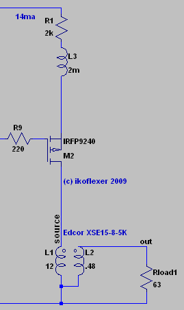
Lowering the value of R1 will increase the gain, and the distortion. Here's a bode plot at R1=2k. Not stellar gain, but for sensitive headphones this might be just fine. It'll have to be played with in reality and see what's what.
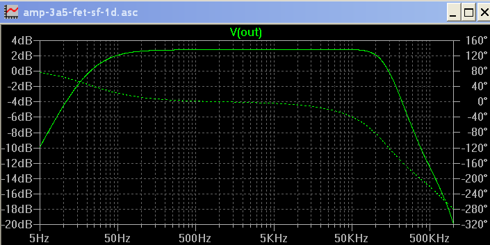
Lowering the value of R1 will increase the gain, and the distortion. Here's a bode plot at R1=2k. Not stellar gain, but for sensitive headphones this might be just fine. It'll have to be played with in reality and see what's what.
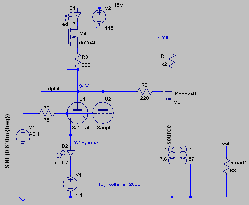
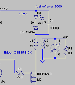
However, the zout bode plot of the output stage shown above does have a spike at about 5kHz. I'm not very happy about that, or about the output stage next, it's a hack, but now the zout bode plot does not have any spikes like that. The zener can be replaced by a few LEDs, or a suitable resistor (680R works). For people worried about the zener tempco, the LED can be replaced by a couple of 1N4148 diodes.
The distortion profile stays the same with this alternate output stage.
Edit: typo
The distortion profile stays the same with this alternate output stage.
Edit: typo
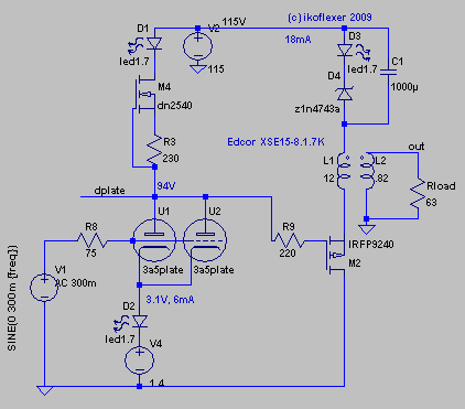
Tried some more transformers with the output stage of previous post. I can't say I'm crazy about that zener in the signal path, but there needs to be a certain voltage drop for the mosfet to be biased properly; I may try a string of LEDs. Another observation is that lower input values to the 3a5 results in a lot of distortion reduction. Then it would make sense to attenuate the input to this amp, and then make an appropriate choice for the output transformer so that the output would be at the wanted level of loudness. The circuit below results in the following simulated distortion figures:
Questionable numbers anyway, and it may also sound like carp, but I think I'll try it out nonetheless.
Also, Lars, the output impedance is now better behaved, I think.
I chose the transformer and other values to match my headphones, of about 63ohms impedance. For other headphones some changes should be in order.
Code:
Fourier components of V(out)
DC component:-2.73218e-007

Harmonic	Frequency	 Fourier 	Normalized	 Phase  	Normalized
 Number 	  [Hz]   	Component	 Component	[degree]	Phase [deg]
    1   	1.000e+03	1.007e+00	1.000e+00	   -1.75°	    0.00°
    2   	2.000e+03	1.213e-04	1.204e-04	   85.02°	   86.77°
    3   	3.000e+03	6.258e-07	6.214e-07	  -48.49°	  -46.74°
    4   	4.000e+03	5.031e-07	4.995e-07	  -78.77°	  -77.02°
    5   	5.000e+03	5.476e-07	5.437e-07	  -79.31°	  -77.57°
    6   	6.000e+03	5.519e-07	5.480e-07	  -76.56°	  -74.81°
    7   	7.000e+03	5.485e-07	5.446e-07	  -74.06°	  -72.31°
    8   	8.000e+03	5.464e-07	5.425e-07	  -71.11°	  -69.36°
    9   	9.000e+03	5.469e-07	5.430e-07	  -68.92°	  -67.17°
Total Harmonic Distortion: 0.012044%
Questionable numbers anyway, and it may also sound like carp, but I think I'll try it out nonetheless.
Also, Lars, the output impedance is now better behaved, I think.
I chose the transformer and other values to match my headphones, of about 63ohms impedance. For other headphones some changes should be in order.
ikoflexer said:Another observation is that lower input values to the 3a5 results in a lot of distortion reduction. Then it would make sense to attenuate the input to this amp]
The lower the swing, the lower the distortion. What's low enough, zero? You can get closer to zero with transistors than with tubes. If you want to obsess over distortion (especially low order distortion), then tubes are not your thing.
Sheldon
Me, if I wanted to try a DHT, I'd start as minimal as possible. A step down transformer on the output, and only enough R's and C's to make it work.
If I wanted to do something fancy or unusual, I'd try filament bias although I'm not sure how well it would work for the 3A5. See this schematic for a really simple circuit: http://www.vinylsavor.de/line01a.gif
After I'd heard the DHT, by itself, then I might try CCS's and mu-followers or whatever.
If I wanted to do something fancy or unusual, I'd try filament bias although I'm not sure how well it would work for the 3A5. See this schematic for a really simple circuit: http://www.vinylsavor.de/line01a.gif
After I'd heard the DHT, by itself, then I might try CCS's and mu-followers or whatever.
ikoflexer said:Thanks salas, nice to see you here, I was beginning to think that I'm shouting alone in the dark
Do yo mean I should still try to simplify?
I meant that page by page you make it simpler and that is nice. I have used CCS on top of triode, even Mosfet Cascode and I did not like it, It gets hard. I prefer a resistor. The only active load I liked was Mosfet Cascode gyrator. Still on the clean side but not hard. If going for DHT triode original tone, prefer resistor. OK, for cleanest + sweetest use choke anode load but its expensive.
- Status
- This old topic is closed. If you want to reopen this topic, contact a moderator using the "Report Post" button.
- Home
- Amplifiers
- Headphone Systems
- Class A, DHT driven, headphone amp