I've had real-world success with a similar circuit to the cascade/cascode (whatever it is called) DN2540s as posted by dsavitsk (/ Doug). However, this is only subjective, as I have no figures or simulations to back it up.
I used 1K stoppers and a pot to set the current at about 25mA. The CCS dropped about 60V as an anode load. It seemed to be fine.
I used 1K stoppers and a pot to set the current at about 25mA. The CCS dropped about 60V as an anode load. It seemed to be fine.
ikoflexer said:
Second suggestion I've tried initially, when I first looked at direct coupling, but couldn't get it working well. Didn't spend much time trying to fix it though, I'll revisit the issue. It'd be nice, of course, to get rid of using a whole lot of parts.
It seems like worrying about direct coupling while leaving that electrolytic on the output is like eating at KFC and ordering a diet drink -- it is least of your worries. Regardless of what bigwill says, the cap will take away from the circuit.
So, why not drop a stage and add a coupling cap between stages and add a servo to the output,
An externally hosted image should be here but it was not working when we last tested it.
or a second mosfet to bring the ground bias up to the same level as the signal,
An externally hosted image should be here but it was not working when we last tested it.
or use a low impedance transformer.
An externally hosted image should be here but it was not working when we last tested it.
ikoflexer said:Regarding the DN2540 ccs; I've also tried that, but for some reason the simulated output impedance was not very good at all. I can give more details if interested.
Not really, as the actual measured results are excellent.
ikoflexer said:As for headphones, I have the run of the mill Sony MDR-V6, claiming 106 dB/mW, 63 ohm at 1kHz. Lack of lots of power (read loud) is not something I worry too much about.
Also, keep in mind that you can most likely leave out the tube stage as your phones only need a fraction of a volt, so you don't need gain. The tube is just a filter here. Why not replace the gain stage if your source with those tubes and just build a current source for the phones?
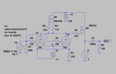
ikoflexer said:sheldon, interesting output stages over at tubecad. Ok, I've simplified the abomination somewhat. Have a look.
You will see the simple ccs load on the 3a5. I use double the jfets (if different Idss the source resistor needs to be adjusted offline until the voltage drop across the two jfets is roughly equal; the reason for this is that the 2sk170 has a 40V Vds max; I know it's a hack, but will look for more suitable jfet, with higher voltage).
Funny, that simple ccs has this output impedance. Over 100kOhm at 1Mhz. Of course, in the real world it's not like that
So, the simpler circuit simulates a bit better for distortion. Nice figures for the voltage on the 3a5 plate (V(dplate)).
I like the resistor load better. It's actually lower on 5th and higher order distortion - which is more dissonant than the low order distortion - assuming it models realistically. I'd still try a resistor load first and see if you like it. I agree with Doug, that the output stage is unnecessarily complicated, and that the coupling cap is not a big issue. I disagree that the output cap (even electrolytic) will necessarily sound bad. Try it, you may like it. Even if you don't want an electrolytic there, you can probably find a 100uf motor run cap or other film cap from a surplus source.
My impression is that this is intended partially as a learning project, which is great. If so, start simple. You can always add complexity, but you may find you like the simple version as well or better than more complicated versions.
Sheldon
Sheldon, the resistor load has higher number in all 9 harmonics. See below.
As for the output stage, unless I can get a simpler version that works just as well, then the more complicated version is not unnecessary. It is a learning project for me, so I'm exploring various topologies and I know some of you disagree with simulation, but it's a great learning tool for me. The spud amp I built behaved almost exactly as I had simulated it before. It was nice to see simulation and reality be very close, and it allowed me to explore very much.
dsavitsk, I am more concerned about the large output cap, that's for sure. But until I switch to OT I'll just have to live with it. Perhaps it's just a dream, but I was thinking of direct coupling two tube stages with that p-channel mosfet schema I showed above (in the future).
About the DN2540 ccs of Gary Pimm. Something doesn't compute, perhaps I made a mistake. To satisfy my own curiosity I'll try to get some of these devices and measure their impedance myself. FWIW the models I used in simulation are from supertex.
Code:
N  CCS        Resistor load
1  1.000e+00 1.000e+00
2  9.492e-05 7.106e-03
3  7.066e-06 1.591e-04
4  1.275e-07 4.994e-06
5  2.602e-07 5.711e-07
6  2.488e-07 5.624e-07
7  2.417e-07 6.734e-07
8  3.246e-07 6.543e-07
9  1.828e-07 6.295e-07
As for the output stage, unless I can get a simpler version that works just as well, then the more complicated version is not unnecessary. It is a learning project for me, so I'm exploring various topologies and I know some of you disagree with simulation, but it's a great learning tool for me. The spud amp I built behaved almost exactly as I had simulated it before. It was nice to see simulation and reality be very close, and it allowed me to explore very much.
dsavitsk, I am more concerned about the large output cap, that's for sure. But until I switch to OT I'll just have to live with it. Perhaps it's just a dream, but I was thinking of direct coupling two tube stages with that p-channel mosfet schema I showed above (in the future).
About the DN2540 ccs of Gary Pimm. Something doesn't compute, perhaps I made a mistake. To satisfy my own curiosity I'll try to get some of these devices and measure their impedance myself. FWIW the models I used in simulation are from supertex.
ikoflexer said:Sheldon, the resistor load has higher number in all 9 harmonics. See below.
As for the output stage, unless I can get a simpler version that works just as well, then the more complicated version is not unnecessary.
I guess I was reading the distortion data incorrectly. I believe that tube will sound good with a resistor load. Also with a current source. Your amp. Your call.
When you say "works just as well". You mean in simulation. I've nothing against simulations at all. But just because something simulates with lower distortion, doesn't mean it will sound better to you. If the goal is to produce an amp that has the lowest possible distortion, then by all means follow the simulations. But if that's the goal, why bother with tubes at all? Heck, a 3A5 doesn't even have a visible glow to warm the psyche. You can always get a more complex solid state circuit to simulate better in that regard than a tube circuit. I'm not sure I see the point in using a tube, then very tightly regulating it's environment, to the point that you could substitute a solid state device in its place without changing the sonics.
Sheldon
Hi Sheldon, sorry if I sounded negative. It wasn't my intention to dismiss your suggestion at all. In fact I appreciate very much your input and I will try the resistor load, listen to it, and then see if I can hear any difference with a ccs load. That being said, if you had seen any of the other struggles of mine in other threads, you would have known where I'm coming from. In the initial stages of a design I tend to explore a lot of different ideas. I use the simulator to dismiss the very horrific ones; there's always the risk of dismissing something that would be good in the real world, but it's a risk I'm willing to take. I build my own models for tubes, from data sheets. The lowest thd is not necessarily what I'm after. But if I see large odd and high number harmonics I tend to think there's something wrong with what I'm doing. Phase shift, stability, are also issues I try to pay attention to. And then I start testing those ideas in reality, with real parts. It's a hobby, what can I say. In the end what doesn't sound good, will be dismissed, I'm man enough to admit when I'm wrong. But I like to convince myself of things and will always keep in mind suggestions I get from you, the more experienced guys.
ikoflexer said:Alright, I'm back.
I should say that I built a 21LU8 based headphone amp (pentode part triode strapped), RC interstage coupling, power transformers re-purposed to OTs. Total cost not more than $50 and it sounds great. Now if I go to a cost of $100 for the DHT amp, it better be twice as good; or so I hope. You may laugh, but that's my personal challenge.
Any chance you could post a schematic for the headphone amp? I have quite a few 6/21LU8's laying around

Thanks!
M1
Of course. You'll find a whole thread following this link
http://www.audiokarma.org/forums/showthread.php?t=163886
The basic schematic is on post #5. I modified it a little (tiny difference in operating points) but it's basically that. I think they're running it in ultralinear mode, I just triode strapped it.
http://www.audiokarma.org/forums/showthread.php?t=163886
The basic schematic is on post #5. I modified it a little (tiny difference in operating points) but it's basically that. I think they're running it in ultralinear mode, I just triode strapped it.
ikoflexer said:Hi Sheldon, sorry if I sounded negative. It wasn't my intention to dismiss your suggestion at all. In fact I appreciate very much your input and I will try the resistor load, listen to it, and then see if I can hear any difference with a ccs load. That being said, if you had seen any of the other struggles of mine in other threads, you would have known where I'm coming from. In the initial stages of a design I tend to explore a lot of different ideas. I use the simulator to dismiss the very horrific ones; there's always the risk of dismissing something that would be good in the real world, but it's a risk I'm willing to take. I build my own models for tubes, from data sheets. The lowest thd is not necessarily what I'm after. But if I see large odd and high number harmonics I tend to think there's something wrong with what I'm doing. Phase shift, stability, are also issues I try to pay attention to. And then I start testing those ideas in reality, with real parts. It's a hobby, what can I say. In the end what doesn't sound good, will be dismissed, I'm man enough to admit when I'm wrong. But I like to convince myself of things and will always keep in mind suggestions I get from you, the more experienced guys.
Hey, no need to apologize. I was just trying to give the reasoning behind the suggestions. It is DIY, and my priorities need not be yours. My experience ain't all that much more than yours. I have learned to appreciate simplicity when it works well. That's the beauty of tube circuits. They can be made simple.
As an aside, I would think that a monotonic phase shift would be much more benign than something lower in magnitude but more irregular. That's just a guess, and may have nothing to do with anything.
BTW, here's a model for 3A5 you can try if you like: http://www.geocities.com/dmitrynizh/3a5-phono.htm
Sheldon
Hey ikoflexer,
Even if the distortion-sims does not tell us how things will sound I am curious how you did them. The reason I ask is as when I use the dmitrynizh-model my sims differ very much from yours.
Did you use the S-command ".options plotwinsize=0" and did you sim over a longer time like 5m to 100m (1u) for 1kHz?
To make it easier to grip/show a Blackman-FFT could also be good to use.
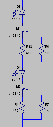
As the cathode is common for both halves of the 3A5 I believe, as mentioned before, it would be better to parallell them, like in a 2A3. See my sketch below. Instead of dry-cell a CCS could of course be used.
Even if the distortion-sims does not tell us how things will sound I am curious how you did them. The reason I ask is as when I use the dmitrynizh-model my sims differ very much from yours.
Did you use the S-command ".options plotwinsize=0" and did you sim over a longer time like 5m to 100m (1u) for 1kHz?
To make it easier to grip/show a Blackman-FFT could also be good to use.
As the cathode is common for both halves of the 3A5 I believe, as mentioned before, it would be better to parallell them, like in a 2A3. See my sketch below. Instead of dry-cell a CCS could of course be used.
Attachments
Sheldon, thanks for the link, I'm familiar with Dmitri's work for a while. I've used that model, but I have some issues with it, so I built my own. I wanted to keep the issue of heater induced hum out of simulations for now, and Dmitri's model differs from others mainly in that; his model of the 3a5 failed in some of my trials and also bogged down the simulations in others. The model I have does follow the RCA data sheet graph except for positive voltages on the grid, a situation that I hope not to encounter in practice.
Here's the model I use.
.subckt 3a5rca P G K
CGP G P 3.2p
CGK G K 0.9p
CPK P K 1p
Bp P K I=(0.006338367588m)*uramp(V(P,K)*ln(1.0+exp((13.17664085)+(13.17664085)*(14.58515197)*V(G,K)/V(P,K)))/(13.17664085))**(1.59420618)
.ends 3a5rca
Lars, I have a few comments about the simulation, plus see above re: Dmitri's model. Yes, I also use no compression and set a very small step size, a small relative tolerance. The simulation command I run is
.tran 0 5.5 5 0.000001 startup uic
and sometimes even longer. I seldom ever use the ideal current source from ltspice. What current are the 3a5s in your sim biased at? The DN2540 current source the way you use it has about 500ohm Zout across the bandwidth. Have a look at the attached image, that's what I got to work really well (awsome output impedance).
I can provide the sim files/models if you'd like.
Attachments
The DN2540 current source the way you use it has about 500ohm Zout across the bandwidth.
Fortunately you are wrong about the above
! A single DN2540 this way will be in the ballpark of 1Mohm(ref Gary Pimm). So it will work good enough. Though I would prefer a higher B+ together with a resistor load. Anyway 4ma/half could be a good start.
revintage said:
Fortunately you are wrong about the above
Yes, I'm glad to be wrong about it as implemented in reality. I meant in simulation. So it wouldn't be much of a good load in your simulations, that's all I'm saying
That ugly variation from my previous post simulates as well as Gary's real tests, that's why I'm using it, as something closer to reality.BTW, I got a jump in distortion at 3.7mA (as the data sheet recommends). Those harmonic results above are at about 2.95mA, and -2.5V on the filament/cathode.
If you prefer higher B+ with resistor load, why not do it that way?
ikoflexer said:The model I have does follow the RCA data sheet graph except for positive voltages on the grid, a situation that I hope not to encounter in practice.
I would think it pretty hard to get an accurate model from the plate curves in the data sheet. Since the data sheet is intended for describing use as a transmitter tube, the resolution for regular class A loads is pretty low. Does it make a difference if you use Dmitri's plate graph?
Sheldn
Sheldon said:
I would think it pretty hard to get an accurate model from the plate curves in the data sheet. Since the data sheet is intended for describing use as a transmitter tube, the resolution for regular class A loads is pretty low. Does it make a difference if you use Dmitri's plate graph?
Sheldn
Excellent point Sheldon! I'll redo the model based on the plate curves and get back to you.
Here we go; left everything the same in the circuit except for the 3a5 model derived from the plate curves on Dmitri's site.
The simulated thd on the plate is 0.023% as opposed to 0.009. The big difference seems to come from the second harmonic. I suppose one can expect even more differences between real life and simulations, but hey, we're in the ballpark.
The simulated thd on the plate is 0.023% as opposed to 0.009. The big difference seems to come from the second harmonic. I suppose one can expect even more differences between real life and simulations, but hey, we're in the ballpark.
Code:
N  3a5_rca  3a5_plate_curves
1  1.000e+00 1.000e+00
2  9.492e-05 2.303e-04
3  7.066e-06 4.354e-06
4  1.275e-07 1.795e-07
5  2.602e-07 2.468e-07
6  2.488e-07 1.389e-07
7  2.417e-07 2.706e-07
8  3.246e-07 2.018e-07
9 1.828e-07 2.740e-07ikoflexer said:Here we go; left everything the same in the circuit except for the 3a5 model derived from the plate curves on Dmitri's site.
The simulated thd on the plate is 0.023% as opposed to 0.009. The big difference seems to come from the second harmonic. I suppose one can expect even more differences between real life and simulations, but hey, we're in the ballpark.
If you can get anywhere close to those values and profile (even the resistor load values), then I'd think that harmonic distortion is not an issue.
Sheldon
So it wouldn't be much of a good load in your simulations
It seems to be a good simmed load that follow Pimms measurements.
About resistive loading vs CCS I did the sketch mainly to show the idea with parallelled 3A5 and simplified SF. The good thing about CCS though, is that you will get a good PSRR.
Nice to hear you did a new Spicemodel based on Hubers curves. Do you mind sharing?
- Status
- This old topic is closed. If you want to reopen this topic, contact a moderator using the "Report Post" button.
- Home
- Amplifiers
- Headphone Systems
- Class A, DHT driven, headphone amp