Hallo to everybody,
I whish to propose to the community my idea regarding a headphone amplifier in SUSY configuration (if Mr. Pass agree….) using well regarded sounding chip LT1210CT7 as a output stage and LME49710 as a input stage. This project is conceived as a Balanced Reference Amplifier for domestic use capable to drive any kind of balanced wired dynamic headphone from 25 to 600 Ohm with negligible distortion at any SPL level.
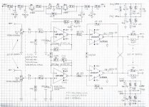
In the attached schematic the proposed implementation:
As a input stage, an instrumentation amplifier configuration is chosen, that give two advantages: The possibility to use balanced or single ended input and above all , proper balanced driving for the next stage in SUSY configuration as suggested from Mr. Pass in a previous discussions regarding SUSY theory.
As I’m not a skilled designer ( this is my first project !), I’m not sure about the DC offset behaviour of this combo. For this particular application I don’t understand if the offset generated by two LT1210 is nulled by the crossed feedback configuration or not.
In any case, I’ve added a very clean offset control circuit (R26/27 should be set for 1-2mA). Is possible to realize this auxiliary circuit in a different and more elegant way using a now again available REF 200 chip from RS Components. Using this chip as in the application note , the voltage swing furnished is less , maybe not enough to null the output offset , considering the low gain of the input stage.
The values for the feedback gain network of the LT1210 are set for maximum flat and extended bandwidth (35/40 MHz for 60/100 Ohm load) and C7/C8 are for capacitive loads stability up to 1000pF. as in case of a 3m. long typical headphone cable.
C5/C6 optional capacitors are for b.w. limiting in case of circuit instability and C3/C4 are for capacitive balancing of opamp inputs when C5/C6 are used.
TR1 is for perfect output gain symmetry of the instrumentation amplifier stage.
R19 is optional load resistor for power supply stability in case of too little current absorption of input stage supply.
In fact , is possible , if desired , to keep separate the power supply lines (doubling the power supply circuits!) for the input and output sections , allowing a optimal power supply rejection between the stages.
Regarding R15 to R18 and R20 to R23 this is to allow a more free choice for the resistors value of the RC supply network.
A “Jung Super Regulator” should be the power supply circuit, due to low PSRR of the LT1210 (50 dB)
Input attenuators:
If the balanced version will be implemented , two double coaxial stepped attenuator are needed for a separate channel volume regulation.
If a unbalanced version will be implemented , one double coaxial stepped attenuator ( or a double coaxial Log. Pot.) is needed for a linked channel volume regulation , while for a separate channel regulation two single stepped attenuator ( or two single Log, Pot.) are needed.
Regarding the layout , will be important the optimal placement of the supply bypass capacitors and well designed star ground returns , the perfect symmetry and equal length of the most critical traces from the output of the first stage and the crossed feedback of two LT1210. In this manner (and using a 0,1% or better precision resistors) , should be ensured the maximal mutual distortion cancellation mentioned in the Mr. Pass papers.
Due to the very fast and wide bandwidth chip used , I think is better to put the circuit , including the input attenuators , in an aluminium box like Hammond series( 188x119x33mm.) with the LT1210 chips fixed at the side walls for the heat dissipation. (the TO220 chips should be located at the border line of the circuit board) . This box , with the power supply circuits ( transformer excluded ) should be placed in a aesthetic box at pleasure.
If this approach to a reference headphone amplifier will be assessed a promising and attractive to a wide audience in the community , is there someone , among the experts and skilled designers in the forum , might like to check or simulate if the project can work properly and good as expected , make it better where it falls and trace a p.c.b. layout ?
Thanks in advance to all those who want to grow this project!
Semola
I whish to propose to the community my idea regarding a headphone amplifier in SUSY configuration (if Mr. Pass agree….) using well regarded sounding chip LT1210CT7 as a output stage and LME49710 as a input stage. This project is conceived as a Balanced Reference Amplifier for domestic use capable to drive any kind of balanced wired dynamic headphone from 25 to 600 Ohm with negligible distortion at any SPL level.
In the attached schematic the proposed implementation:
As a input stage, an instrumentation amplifier configuration is chosen, that give two advantages: The possibility to use balanced or single ended input and above all , proper balanced driving for the next stage in SUSY configuration as suggested from Mr. Pass in a previous discussions regarding SUSY theory.
As I’m not a skilled designer ( this is my first project !), I’m not sure about the DC offset behaviour of this combo. For this particular application I don’t understand if the offset generated by two LT1210 is nulled by the crossed feedback configuration or not.
In any case, I’ve added a very clean offset control circuit (R26/27 should be set for 1-2mA). Is possible to realize this auxiliary circuit in a different and more elegant way using a now again available REF 200 chip from RS Components. Using this chip as in the application note , the voltage swing furnished is less , maybe not enough to null the output offset , considering the low gain of the input stage.
The values for the feedback gain network of the LT1210 are set for maximum flat and extended bandwidth (35/40 MHz for 60/100 Ohm load) and C7/C8 are for capacitive loads stability up to 1000pF. as in case of a 3m. long typical headphone cable.
C5/C6 optional capacitors are for b.w. limiting in case of circuit instability and C3/C4 are for capacitive balancing of opamp inputs when C5/C6 are used.
TR1 is for perfect output gain symmetry of the instrumentation amplifier stage.
R19 is optional load resistor for power supply stability in case of too little current absorption of input stage supply.
In fact , is possible , if desired , to keep separate the power supply lines (doubling the power supply circuits!) for the input and output sections , allowing a optimal power supply rejection between the stages.
Regarding R15 to R18 and R20 to R23 this is to allow a more free choice for the resistors value of the RC supply network.
A “Jung Super Regulator” should be the power supply circuit, due to low PSRR of the LT1210 (50 dB)
Input attenuators:
If the balanced version will be implemented , two double coaxial stepped attenuator are needed for a separate channel volume regulation.
If a unbalanced version will be implemented , one double coaxial stepped attenuator ( or a double coaxial Log. Pot.) is needed for a linked channel volume regulation , while for a separate channel regulation two single stepped attenuator ( or two single Log, Pot.) are needed.
Regarding the layout , will be important the optimal placement of the supply bypass capacitors and well designed star ground returns , the perfect symmetry and equal length of the most critical traces from the output of the first stage and the crossed feedback of two LT1210. In this manner (and using a 0,1% or better precision resistors) , should be ensured the maximal mutual distortion cancellation mentioned in the Mr. Pass papers.
Due to the very fast and wide bandwidth chip used , I think is better to put the circuit , including the input attenuators , in an aluminium box like Hammond series( 188x119x33mm.) with the LT1210 chips fixed at the side walls for the heat dissipation. (the TO220 chips should be located at the border line of the circuit board) . This box , with the power supply circuits ( transformer excluded ) should be placed in a aesthetic box at pleasure.
If this approach to a reference headphone amplifier will be assessed a promising and attractive to a wide audience in the community , is there someone , among the experts and skilled designers in the forum , might like to check or simulate if the project can work properly and good as expected , make it better where it falls and trace a p.c.b. layout ?
Thanks in advance to all those who want to grow this project!
Semola
Attachments
- Status
- This old topic is closed. If you want to reopen this topic, contact a moderator using the "Report Post" button.