Am I anywhere close with this? What I did was take a schematic for the LM386 as an amp with bass boost and added the LF353N as a buffer. I really don't understand what every thing does. I am displaying my ignorance of basic curcuitry so please don't laugh if this is nowhere close. 
Thanks
Jeremy
Thanks
Jeremy
Attachments
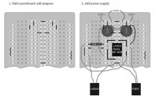
OK, small changes:
remove pot and 10K from input, input jack directly to buffer's pin 3, 1Mohm from pin 3 to ground.
Now you have high impedance (1 Mohm) input buffer.
Between stages - remove 10k resistor, put in this place 10-20K pot, like in original LM386 schematic (you see in datasheet, right?).
BTW, I am not sure you need with bass boost, try simple 20 gain schematic first.
Zigis.
Zigis said:I see in some schematics 10mf
And don't forget, for LF353 you need +- PS (virtual ground) and for LM386 simple PS.
Maybe more easy way is to build on LF353 only, one channel as input buffer, second as amp with gain 10-15 (Cmoy stile). This is mono, for instrument only.
Since I don't understand the virtual ground, could you point me to a cmoy style schematic that is based for an instrument that would work with the lLF353? The only ones I can find are for boosting an ipod or cd player. Could I use one of those and just add the buffer? Maybe this one? http://tangentsoft.net/audio/cmoy-tutorial/misc/cmoy-tangent-sch.pdf
Yes, you can use schematic you posted, and put before pot your buffer with 1 M input resistor.
With instrument you can bypass C2, there is not DC in guitar's pickup (if you don't use any effect box or pedal ).
Virtual ground in this schematic create two 4.7Kohm resistors R1+ and R1-.
With instrument you can bypass C2, there is not DC in guitar's pickup (if you don't use any effect box or pedal ).
Virtual ground in this schematic create two 4.7Kohm resistors R1+ and R1-.
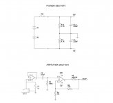
OK Here's what I ended up building. Its a variation of a C-moy amp, using half as the buffer and half as the amp. I am getting absolutely nothing. No sound, crackling only silence. I tried with one 9 volt battery and with two. I think all of my soldering is good, but I can't guarantee that my parts are right as I made some of the changes myself.
Here is the schematic that I altered, and a picture of the board as I built it. Thanks for any advice.
Here is the schematic that I altered, and a picture of the board as I built it. Thanks for any advice.
Attachments
Hi,
I can't see R4 connected to opamp's output pin 7, try to connect it.
If you get amp working, few things to change:
you forget pot between both stages, be carefully, it could be loud!
connect feedback resistor R4 between pins 6 and 7 in way you do with others resistors, it is good to make feedback loop physically as short as possible,
you can remove C2, connect buffer's out directly to next stage in (better with pot between), there is no DC source in guitar.
That helped a bunch zigis. I added R5 the optional one shown in the schematic. I used the same resistor as R4 (10K).
Here's where I'm at.... I have sound now. sounds very distorted though. The volume wouldn't get very loud even with the guitar turned all the way up. I wonder if I should have just used a jumper instead of a resistor at R5?
I will add the 10K pot when I get one. I figured the one on the guitar would work for now. Also if I take C2 out what would I do there? Just a jumper? I figured on putting the pot on the wire between C2 and pin 1.
Thanks again for the advice.
Also I am using (2) 9 volt batteries, should I only use one?
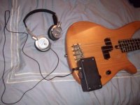
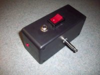
Perfect!!!!!!!!!!! It's done! I installed it in the project box and added an on off switch and it works like a charm. Bass or regular guitar. I can't tell you guys how much I appreciate the help.
Zigis, walking a novice like me through it step by step was a great help! I really appreciate you taking the time to look it over for me and give me great advice.
Now that I have the basic concept down, I may try one with two sides so I can play an ipod through it as a jam-a-long. but I'm going to enjoy the one I built for awhile first.
Jeremy
One more question. If I was to make a left and a right channel, could I (on one of the channels) have an input after the buffer and an input before the buffer? One for the right channel of an ipod and the one before the buffer for the guitar?
I need three inputs total and I'm trying to figure out if I would get some weird voltages or something by doing this. Basically I would use the same schematic that I used on the bass amp, but with another channel added with no buffer for the other side of the ipod.
Sorry if I'm asking too many questions. I got the first one working (with a lot of help from here) and now I'm ready to step it up a bit!
jman
I have a question about the buffer on the amp that I built. I have a pretty good grasp of why its there.....but, I built the exact same amp with no buffer or 1M resistor on the input and it sounds exactly the same.
I understand that the 1M resistor is there to set the input inpedence. I don't have a scope so I can't see exactly what its doing, but I can't hear any difference without them.
Is it hard on the equipment if they are not included or if it performs OK is is alright to leave it out?
I understand that the 1M resistor is there to set the input inpedence. I don't have a scope so I can't see exactly what its doing, but I can't hear any difference without them.
Is it hard on the equipment if they are not included or if it performs OK is is alright to leave it out?
- Status
- This old topic is closed. If you want to reopen this topic, contact a moderator using the "Report Post" button.
- Home
- Amplifiers
- Headphone Systems
- Bass Guitar Headphone Amp?