I am making an ELS headphone. So far I am biasing it at around 1200V. But yet, the sound is still too soft. I am using a 6L6 SE tube amp to drive it though. I wonder if I were to use a more powerful amp to drive, will I get louder sound?
By the way, my spacer is 0.5mm and I am using "food plastic wrap" as diaphragm.
By the way, my spacer is 0.5mm and I am using "food plastic wrap" as diaphragm.
Attachments
")
hi,
well, i built an esl headphone a few years ago, unfortunately it was destroyed in a car accident...
but, one thing i can tell you for sure, there is no need for 1200v bias in an esl headphone!
i ran mine at around 600v, driven by a 6sn7 amp and volume was plenty (though we might have different spl requirements...)
brgds
michael
I use a line transformer 100V / 4 ohm to connect to my diaphragm and stators and use a 6L6SE amp connecting through its 8 ohm output to 4 ohm of the transformer. I am going to try 8 to 8 ohm and 8 to 16 ohm.
Well, I guess I need to build an amp for it. Any suggestion on the circuit?
Wachara C.
Well, I guess I need to build an amp for it. Any suggestion on the circuit?
Wachara C.
I use liquid soap for coating the diaphragm.
How do you measure the output of the 100V transformer?
One side of the transformer is connected to the amp and the other side to the stator. So, I really don't know how to make a measurement.
Will it be okay to connect the transformer to output of a pre amp instead? Will the sound be even less?
How do you measure the output of the 100V transformer?
One side of the transformer is connected to the amp and the other side to the stator. So, I really don't know how to make a measurement.
Will it be okay to connect the transformer to output of a pre amp instead? Will the sound be even less?
i'm just guessing, but your preamp wont be able to drive it.
well, to measure it you need a signal source and a volt meter, connect the voltmeter across the secondaries our your transformer and apply a sine to the input of your setup...
(if you don't have a signal gen. there are a lot of free ones for your pc)
don't zap yourself ;-)
maybe the mass of your diaphragm is to high?
michael
Michael,
Thanks for your info. I do not have a signal generator and I do not understand its usage. Could you kindly explain to me what to look for when you make a measurement using a signal generator?
The diaphragm I use is actually the plastic wrap that you wrap on your food when you microwave. I do not know its thickness, but it is very thin. The thinnest I can find around here.
Wachara C.
Hi,
go to a TV repairman and ask him to tell you the step up rate.
Where did you get the transformer from?
It all sounds to me, that the bais is way too high and has sucked
the diaphragm into the statorplate. This happened when I build
a headphone 33 jears ago, not enough stretched the thing,
because I wanted bass. You also should support the membrane
in the center to both sides with silicone dots.
There was a nice DIY headphone design in the
GB mag "Wireless World" Nov. 1979, which I can send you by email,
because it is to lage for an attachment here.
Regards
Frank
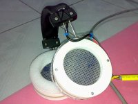
PS: Your headphone looks a lot nicer than mine looked!
Very nice!
go to a TV repairman and ask him to tell you the step up rate.
Where did you get the transformer from?
It all sounds to me, that the bais is way too high and has sucked
the diaphragm into the statorplate. This happened when I build
a headphone 33 jears ago, not enough stretched the thing,
because I wanted bass. You also should support the membrane
in the center to both sides with silicone dots.
There was a nice DIY headphone design in the
GB mag "Wireless World" Nov. 1979, which I can send you by email,
because it is to lage for an attachment here.
Regards
Frank
PS: Your headphone looks a lot nicer than mine looked!
Very nice!
Andrew radford has done it
I found this web page by Andrew Radford a few months ago - it looks informative, and I was going to copy his example.
http://www.headwize.com/projects/showfile.php?file=radford1_prj.htm
I found this web page by Andrew Radford a few months ago - it looks informative, and I was going to copy his example.
http://www.headwize.com/projects/showfile.php?file=radford1_prj.htm
frank ziel said:Hi,
go to a TV repairman and ask him to tell you the step up rate.
Where did you get the transformer from?
It all sounds to me, that the bais is way too high and has sucked
the diaphragm into the statorplate. This happened when I build
a headphone 33 jears ago, not enough stretched the thing,
because I wanted bass. You also should support the membrane
in the center to both sides with silicone dots.
There was a nice DIY headphone design in the
GB mag "Wireless World" Nov. 1979, which I can send you by email,
because it is to lage for an attachment here.
Regards
Frank
PS: Your headphone looks a lot nicer than mine looked!
Very nice!
Thank you very much for your info. I'll check if the diaphragm is ok.
I'm very interested in the magazine. I'll send you an email.
Re: Andrew radford has done it
That's exactly where I get my design from.
Wachara C.
Steerpike said:I found this web page by Andrew Radford a few months ago - it looks informative, and I was going to copy his example.
http://www.headwize.com/projects/showfile.php?file=radford1_prj.htm
That's exactly where I get my design from.
Wachara C.
Hi,
the 0.4mm of d/s should be fine to get earsplitting levels. Especially so with nearly unbelievable high polarizing voltage of 1.2kV. Commercial Designs like the Stax et al usually work with less than 600V! 1200V can´t be the real value, because it´s way above the arcing limit of air anyway. So I assume that the ´real´ polarizing voltage will be just around 500-700V or even less.
The soft sound may come from the membrane material. Even though it looks very thin, it´ll be too thick for ESL usage. The thinnest film I can get here in a supermarket is 18µm thick, which is too much and too heavy to reach complete audio bandwidth (freq-response will probabely start to drop above 5-10kHz. For Headphones You need the thinnest possible material, if possible below 2.5µm.
Liquid soap is a quite good membrane coating.....for maybe a week.
You should use a more stable material which adds less mass too, e.g the glue-formula (search the forum for membrane coating)
The last point regards the used transformer. When it shows high leakage inductance values the bandwidth of the system Panel/Transformer will resonate below 20kHz, thereby limiting the bandwidth to values below 20kHz.
jauu
Calvin
Hi,
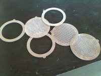
I´ve just taken a closer look at your pics. Am I right in that You use some kind of PCB-like material with the stator´s conductive side to the outside?
If so, Your d/s will not be 0.4mm but 0.4mm+ thickness of the stator insulation. If for example You use normal 1.5mm FR4, Your d/s would be 1.9mm. Than 1.200kV of polarizing voltage would not only be allowed for the headphones not to arc, but it would actually be quite a bit low. The problem with this large d/s is now that the capacitance of the headphone drops to very small values. A small capacitance means high impedance values. So You´d need a transformer with a very high transformation factor. Otherwise the impedance mismatch between driving amp and load would be too great, hence the headphone would play at only very low levels.
A last remark. If the holes in the stator are small and the stator is relatively thick, the holes start acting like a Bassreflex-channel! The bandwidth of the sum of the channels can easily drop below 20kHz.
So even if everything else is alright, the dimensions, shape and number of holes in the stator could ruin a good result.
jauu
Calvin
Dear Calvin,
Thanks for your input.
Yes, I use 1 mm PCB material as the stators. I cut them using my DIY cnc machine. I put the copper side inside and with a plastic spacer then a piece of diaphragm, spacer, and PCB with the copper side facing the diaphragm. So the thicknesses are 1 mm, 0.5 mm, diaphragm (thickness?), 0.5 mm, and 1 mm respectively.
The holes are 2 mm. I didn't know the shape and stator holes play a so important role. Could you please let me know what the ideal shape and dimension of the holes should be?
I played with a different diaphragm and spacer today. Interestingly, I found the sound from thicker spacers (1mm) and somewhat thicker diaphragm actually was louder with the same level of bias voltage and input volume compared to the previous one. My guess was that my old one had actually a problem with diaphragm arching to either side of the stator. I am going to use this same diaphragm with the 0.4 mm spacer to see what will happen. Will keep you inform.
Wachara C.
- Status
- This old topic is closed. If you want to reopen this topic, contact a moderator using the "Report Post" button.
- Home
- Amplifiers
- Headphone Systems
- Has anybody made an ELS headphone?