Hi Vaughn,
After the meeting, four other friends were rushing me for the kits.
It's a really fun meeting and we were impressed at how good a DIY headphone could sound.
About the loud speakers, I would really need a lot of help. I will start a new thread soon and hope that you guys can help me out.
Wachara C.
After the meeting, four other friends were rushing me for the kits.
It's a really fun meeting and we were impressed at how good a DIY headphone could sound.
About the loud speakers, I would really need a lot of help. I will start a new thread soon and hope that you guys can help me out.
Wachara C.
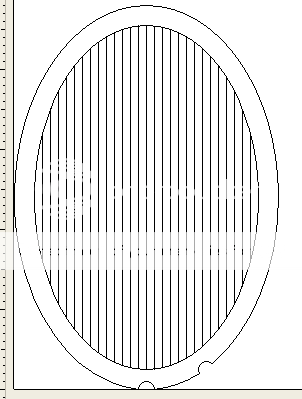
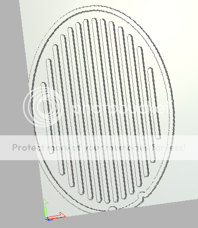
frank ziel said:Hi, Wachara
dont' you think it will be better
to turn the direction of the slots 90°,
because then the distance to the frame
is much shorter as it is now?
Regards
Frank
Hi Frank,
Thanks for your comment. I've never thought of that, actually.
I'll think about it.
Wachara C.
")
@Philippe:
Hi Philippe,
can you make a little experiment with the two
different electrodes you made?
I think this will help us to understand why the ones with piano-wire sounds better than the ones with holes!
Lite a cigarette (pipe, cigar)
Take the elektrodes one after the other in the same distance (10cm)
in front of your mouth and then blow smoke gentle (!) at them.
Best you sit in front of a mirror, that you can see what happens
(or what comes out) on the other side.
Don't inhale ...
Regards Frank
Hi Philippe,
can you make a little experiment with the two
different electrodes you made?
I think this will help us to understand why the ones with piano-wire sounds better than the ones with holes!
Lite a cigarette (pipe, cigar)
Take the elektrodes one after the other in the same distance (10cm)
in front of your mouth and then blow smoke gentle
(!) at them.Best you sit in front of a mirror, that you can see what happens
(or what comes out) on the other side.
Don't inhale ...
Regards Frank
Round and rectangular
I did experiences with large and small loudspeakers. (1000 mm * 800 mm and 50 mm radius, a rectangular, round)
The round loudspeakers has one resonance, other form of a loudspeakers TWO resonances.
The more resonances at a loudspeakers, the it is worse.
I am sorry for my English.
I did experiences with large and small loudspeakers. (1000 mm * 800 mm and 50 mm radius, a rectangular, round)
The round loudspeakers has one resonance, other form of a loudspeakers TWO resonances.
The more resonances at a loudspeakers, the it is worse.
I am sorry for my English.
Re: Round and rectangular
Hi Kontra,
Do you mean that round shape is better than rectangular?
Wachara C.
Kontra said:I did experiences with large and small loudspeakers. (1000 mm * 800 mm and 50 mm radius, a rectangular, round)
The round loudspeakers has one resonance, other form of a loudspeakers TWO resonances.
The more resonances at a loudspeakers, the it is worse.
I am sorry for my English.
Hi Kontra,
Do you mean that round shape is better than rectangular?
Wachara C.
The round loudspeakers has one resonance, other form of a loudspeakers TWO resonances.
Actually, in both cases there is one fundamental resonance, and a (theoretically infinite) number of higher frequency modes. The higher frequency modes generally have more nodes than the lower frequency modes, although the details depend on the rectangular diaphragm's ratio of the length to width.
For some nice animations of the circular membrane's modes, see this site. The modes of the rectangular membrane can be seen here.
Few said:
Actually, in both cases there is one fundamental resonance, and a (theoretically infinite) number of higher frequency modes. The higher frequency modes generally have more nodes than the lower frequency modes, although the details depend on the rectangular diaphragm's ratio of the length to width.
For some nice animations of the circular membrane's modes, see this site. The modes of the rectangular membrane can be seen here.
Thanks for that Few, those are some very interesting simulations...
I don't know that we'll ever know without some fancy test equipment what the best shape is
for a diaphragm. For some reason I think it is neither circular, ovoid, rectangular, etc. but
something else entirely not based on simple geometry. Or perhaps to think laterally use a traditional
geometric shape but somehow be able to vary tension on the diaphragm in a fixed (or even dynamic) way
that would allow you to suppress/cancel certain resonances. The problem (at least in the past) with making
a more complex shape is in the "economy of production". It has been cheaper to make circles, ovals and rectangles than a complex shape.
It seems that the top electrostatic headphones don't rely on one standard shape; The Stax Omega has a circular
diaphragm and the Sennheiser HE60/90 have oval ones. The new crop of electrostatic headphones coming out of China seem to be all using oval diaphragms.
About width of a film and a bass
Hi, Wachara
It seems to me, I know, why so it seems to you.
The thin film is more inclined to be shaded slide as the piston
" Wants or can " do it better than thin.
Because " it is easier to thick film to be the piston "
The the film is more thin, the it is more on it than tracks of movement between two perforated leafs.
Adout roud loudspeakers: I think round better than rectangular, because it is not necessary to undertake express methods to kill rezonance. First of all.
I think, that round it is better because issues " a magic sound "
And as this authoritative judgement for me thinks Staxx.
Hi, Wachara
chinsettawong said:Last night I had a chance to try the 0.9 microns mylar which I bought from the USA. Interestingly, I didn't find the diaphragm to be more efficient than the 6 microns one. Overall, the mid and high sounded about the same as the 6 microns. But the low frequency wasn't as good.
I'll try the 1.4 micron mylar tonight, and will report soon.
Wachara C.
It seems to me, I know, why so it seems to you.
The thin film is more inclined to be shaded slide as the piston
" Wants or can " do it better than thin.
Because " it is easier to thick film to be the piston "
The the film is more thin, the it is more on it than tracks of movement between two perforated leafs.
Adout roud loudspeakers: I think round better than rectangular, because it is not necessary to undertake express methods to kill rezonance. First of all.
I think, that round it is better because issues " a magic sound "
And as this authoritative judgement for me thinks Staxx.
Re: About width of a film and a bass
The first version of my headphone is a round one. I like it very much. However, I don't feel that it sounds better than my oval shape version.
Wachara C.
Kontra said:Hi, Wachara
It seems to me, I know, why so it seems to you.
The thin film is more inclined to be shaded slide as the piston
" Wants or can " do it better than thin.
Because " it is easier to thick film to be the piston "
The the film is more thin, the it is more on it than tracks of movement between two perforated leafs.
Adout roud loudspeakers: I think round better than rectangular, because it is not necessary to undertake express methods to kill rezonance. First of all.
I think, that round it is better because issues " a magic sound "
And as this authoritative judgement for me thinks Staxx.
The first version of my headphone is a round one. I like it very much. However, I don't feel that it sounds better than my oval shape version.
Wachara C.
Hi,
aaah, You found the glue-formula
Instead of graphite You may try black writing ink.
my recipe for 100mL of coating is:
1 volume part glue (Tesa brand)
4 volume parts destilled, deionized water
2 tiny drops of black writing ink
The black ink contains extremely fine particles of carbon black in a water based solution. So it dissolves easily and You can taylor the resistance to Your needs depending on the number of drops of ink and the thickness of the wet coating.
It can be brushed on (extremely thin) or sprayed onto the film and the film can be coated a 2nd or 3rd time to reduce the resistance, if the resistance of a single coating prooves too high.
Films coated this way are working stable for many years.
The color of the solution is slightly greyish and the dryed coating is almost invisible.
jauu
Calvin
Thanks Calvin. Tesa seems to make lots of different types of adhesive. Is this the one you're referring to?
Few
An externally hosted image should be here but it was not working when we last tested it.
Few
Hi,
the link is not the right Tesa. It´s the bottle with the red cap, which reads ´Alleskleber´ i.e ´all-purpose glue´ and `wasserfest´ i.e ´waterproof´ on the label.
The correct Tesa comes in the bottle with a blue cap and reads ´Vielzweckkleber´´i.e ´multi-purpose glue´ and ´ohne Lösungsmittel´ i.e ´free of solvents´ on the label.
The kind of glue makes the difference. Tests with UHU glue which looks smells and tastes the same failed completely.
jauu
Calvin
Calvin said:Hi,
the link is not the right Tesa. It´s the bottle with the red cap, which reads ´Alleskleber´ i.e ´all-purpose glue´ and `wasserfest´ i.e ´waterproof´ on the label.
The correct Tesa comes in the bottle with a blue cap and reads ´Vielzweckkleber´´i.e ´multi-purpose glue´ and ´ohne Lösungsmittel´ i.e ´free of solvents´ on the label.
The kind of glue makes the difference. Tests with UHU glue which looks smells and tastes the same failed completely.
jauu
Calvin
Wow! Did you really try to taste it, Calvin?
Wachara C.
Hi,
Yeah, why not? It´s not poisonous if swallowed (I assume it was intended as child friendly hobby-glue), but You don´t need to swallow it when You just wanna taste ;-)
There seem to be no ill effects, but I sometimes wonder about the fact that my communication has reduced to hammering words into a keyboard *lol*
jauu
Calvin
Hi,
regarding wachara´s Q in post #101:
The high valued resistance has the purpose to keep the charge constant. Done as a simple series resistance and using a highly conductive membrane coating the charge would remain constant, but not the distribution of charge over the membrane area. The charge would concentrate at points which are closer to a stator. This concentration would mean a higher force on the membrane at this point, pulling the membrane closer to the stator, more charge concentrating at this spot and so on. This is a self energizing effect and introduces non-linearities, hence distortion.
Therefore it has become quite a standard to use a highly resistive coating that ´fixes´ the charge at its place. Besides this reduces the energy of a flashover, so that it remains a ´cold´ flashover and doesn´t turn into a hot spark that could melt holes into the film.
A lower resistance reduces charging time, that´s right, but this only plays a role when You power-up the system the first time. Assuming a well build panel with low leakage (ideally no leakage) the charge remains constant for several seconds if not a few minutes (ideally it stays on forever). Even a rather slow highvoltage cascade (50Hz/60Hz) together with a high series resistance is fast enough to make up for the loss of charge on the membrane.
Still though a too high valued coating seems not to be able to hold enough charge to reach field saturation (-->lower force, lower efficiency), since it forms a voltage divider with the air resistance, i.e. leakage path, towards the stators. The best compromise seems to be around 10^8---10^11Ohms/sqr of surface resistance.
jauu
Calvin
Hi Calvin,
Thank you so much for your explanation. I had actually proved it to myself that high surface resistance was actually better. I did an experiment to coat the diaphragm with very low resistive value - less than 1k ohms. I tried to listen to the music and the music was very distorted.
Wachara C.
Thank you so much for your explanation. I had actually proved it to myself that high surface resistance was actually better. I did an experiment to coat the diaphragm with very low resistive value - less than 1k ohms. I tried to listen to the music and the music was very distorted.
Wachara C.
- Status
- This old topic is closed. If you want to reopen this topic, contact a moderator using the "Report Post" button.
- Home
- Amplifiers
- Headphone Systems
- Has anybody made an ELS headphone?