Well its been a long time and no DIY, but I've rocketed back ... abiet with an easy project. Here is my CMOY headphone amp. I guess I missed the boat on these as I just found out about them. I assume that like Gainclones most everyone here has made one by now. The sound is really nice through my Grado SR60s, I'm going to try the AKG's next.
Here is my link for this project- CMoy Amplifier (its not on the main page yet).
I've got multiple inputs/outputs and +/- 9VDC with the virtual ground chip. Kind of a neat little box, just need to find a volume knob to go on the potentiometer. I used the PCB that came with the case to hold the other items, using only the traces for power and LED illumination. There are small soft pieces of felt under a few items so that the uneven green board does not puncture anything important, and it keeps the capacitors nice and comfy. Best part is, I made this with left over DIY parts so the entire cost of this was less than $15.00 (not including the batteries).
An externally hosted image should be here but it was not working when we last tested it.
An externally hosted image should be here but it was not working when we last tested it.
An externally hosted image should be here but it was not working when we last tested it.
An externally hosted image should be here but it was not working when we last tested it.
CMoy performance
Here is some performance data-
This easily puts out over 10v pk-pk into 400 ohms, but I was wondering how it does into low impedances.
Here it is at 20 Hz into 10 ohms (actually 10.1 ohms) at 0.2 V/Div.

Here it is at 1KHz into 10 ohms at 0.2 V/Div.

I figure about 3 div at 20 Hz, so 60 mA and about 80 mA at 1KHz.
What do you think?
Here is some performance data-
This easily puts out over 10v pk-pk into 400 ohms, but I was wondering how it does into low impedances.
Here it is at 20 Hz into 10 ohms (actually 10.1 ohms) at 0.2 V/Div.
Here it is at 1KHz into 10 ohms at 0.2 V/Div.
I figure about 3 div at 20 Hz, so 60 mA and about 80 mA at 1KHz.
What do you think?
mjf said:hello.
i looked at the schematic in post 1.
it seems that c1 & r2 (at the input of the opamp) show a -3db cutoff round about 70 hertz, doesn't it cut off the bass?
isn't r2=100k in the original schematic (would give you 7hz......)?
what happend?
greetings.................
Yipes, I hope not, since I used .22uF caps instead of .1 uF to avoid low freq. attenuation!
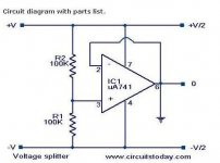
This is a mistake in the schematic, thank you, I will fix it. I remember that I did not have a 100K on hand so I used two 51K resistors in series as you can (barely) tell from the pictures.
Also, I would note that the clipping point didn't change depending on using a pair of 9V batteries or the DC adaptor from the wall (15 volts, 500 mA). You do get a little hum/noise from the wall adaptor on efficient headphones that you do not get from the batteries, which are very quiet.
What I don't understand is how I get 60 mA out of these when the virtual ground chip is limited to about 35 mA and the opamp is also about 35 mA.
- Status
- This old topic is closed. If you want to reopen this topic, contact a moderator using the "Report Post" button.