The majority of headphones have quite simply awful high-frequency performance. However, by using either a single ribbon or a combination of ribbons, it should be possible to build a driver that works very well even to high frequencies with minimal energy storage. Also, according to another DIYaudio thread, the ribbon could reproduce an acceptable amount of bass, too - the short length would apparently keep it from "flapping" at low impedances.
Transmissionaudio.com has a picture of a prototype on their page, too.
http://www.transmissionaudio.com/ourribbons.html
The obvious problems with this setup would be weight (enormous) and impedance (tiny.) However, these would likely never leave my desk, and if I can get some metallized Kapton film, it should be possible to etch fine enough traces to get the impedance to an acceptable (1-ohm?) level.
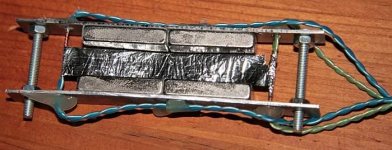
jzagaja said:One of very first ugly ribbon headphone I've made from capacitor foil. More than enough bass. SPL limited but sufficient. Pleasant sound. Almost cost nothing. Can fit into Skype headphones easily (open air is however better).
Very interesting. How do you compensate for the incredibly low impedance of such a short piece of foil?
jzagaja said:This is headphone measurement (6mm electret mike, 5mm above membrane in the middle), room noise. Corrugated ribbon could be better because excursion is rather large (4mm).
That is an impressive measurment indeed. What cap did you get the film from? And how could I wind an appropriate transformer?
Necessary parts can be taken from old TV, radio and PC power supply (transformer core) or any other electronic waste.
1) Ribbon source is styroflex cap:
http://www.radiomuseum.org/forumdata/users/1146/Styroflex.jpg
Smaller the rated voltage thinner the foil. My LCR meter says 10um.
2) Wire (copper enamelled wire, magnet wire) from larger coils (short length) or typical home EI AC/DC adapter. Disassembly takes at least 30 minutes but you can rewind such a transformer for your ribbon as well.
3) Transformer core. PC PSU has larger cores. Core size and material determines power rate, distortion and inductance on secondary (amplifier side). Better the core less wire is necessary for a target inductance (low freq. -3dB point). Typical ribbon transformers has inductance of a few mH. Ribbon speaker has inductance of L2 coil related to LR4 crossover.
Minimum turns on secondary:
=V*10000/(4,44*freq*core_area_cm2*Bmax)
Ferrite core: 10V, 20Hz, 1cm2, 0.5T gives 2252 turns - that's a lot.
Primary (ribbon) side requires low DC resistance (DCR). Tenth of ribbon resistance - magnet wires connected in parallel. Divide above turns by squared transformer ratio = target impedance/ribbon resistance.
Quick and dirty layout:
50 turns of secondary
foil layer
10 turns of primary
foil layer
50 turns of secondary
Should work however ferrite core will saturate a bit.
Transformer transmittance and impedance can be evaluated with ARTA: www.fesb.hr/~mateljan/arta/
Requires stereo mic or line input in your PC.
Appended picture shows best balanced armature motor (single) in Shure E2 in-ear headphone. Midrange resonance isn't good on many recordings. Dipole ribbon, open construction is much more comfortable. Shure cannot be used for binaural playback.
Attachments
I've been working on this idea. Due to my extreme inability to use FEMM, I've even enlisted the help of a fellow at the local university. (Being a student has perks, I suppose.)
However, instead of the massive headaches of transformers, I'm thinking of using metal foil on kapton. If I have my math right, six 4" long traces of 4 micron aluminum foil wired in series will have a DCR of 2.1 ohms - easily driven by a solid-state amplifier.
One thing that surprises me is how well the bass measured. From what I understand, a full waveform is unable to form due to the short distance between ear and transducer, so a good-quality seal is needed. However, a ribbon may actually have greater excursion than many headphone transducers, so this may be a non-issue.b
Usually metalic pattern is added to plastic foil via oil print. Check the math - several Ohms @ 4um is possible for longer ribbons - few meters long but if the trace is narrow... Capacitor manufacturers can produce serpentine pattern on paper or any foil but the tooling cost ca. 700 Euro. Typical 50m coils of metalized paper (alu and zinc) costs 50 Euro each. I'll check possible resistivity. Total thickness is quite good: 8-16um.
There's a really deep bass from above orthodynamic headphone - depends on distance from membrane. Escursion can be really large so good mechanical clamping is essential.
There's a really deep bass from above orthodynamic headphone - depends on distance from membrane. Escursion can be really large so good mechanical clamping is essential.
I strongly suggest practise with small planar headphone. Take a small photo frame and cut kitchen foil using frame glass. Attach foil to frame with scotch tape - chose appropriate tension. Put neodymium magnets in rows (opposite polarity) and attach to the metal sheet. Leave elsewhere. Now cut 50mm wide aluminium tape (to the frame width) as shown on the picture and stick to the foil (hardest step). Connect ending to the headphone out - kitchen radio is ok. Put your frame as close magnets as possible and enjoy. You'll be amazed with the sound. Everything depends on membrane tension. You should hear very deep bass. Checked with Marcus Miler ")
Attachments
jzagaja said:I strongly suggest practise with small planar headphone. Take a small photo frame and cut kitchen foil using frame glass. Attach foil to frame with scotch tape - chose appropriate tension. Put neodymium magnets in rows (opposite polarity) and attach to the metal sheet. Leave elsewhere. Now cut 50mm wide aluminium tape (to the frame width) as shown on the picture and stick to the foil (hardest step). Connect ending to the headphone out - kitchen radio is ok. Put your frame as close magnets as possible and enjoy. You'll be amazed with the sound. Everything depends on membrane tension. You should hear very deep bass. Checked with Marcus Miler
This may be a better solution.
I'd like to find a thinner foil, though.
Nice to see another foray into ribbon headphones.
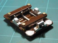
Here is a pic of a transducer i made a while back, it uses a coil etched on a flexi circuit material.
The pic shown has more turns than the final version.
I have made several pairs of phones using the design , and they sound rather nice.
I still have a new and improved version the transducer on the drawing board, but the project has been on hold for the last few years.
Mark
Attachments
![transducer-mk2[a].jpg](/community/data/attachments/93/93623-10a8d512d3af447d19398e4ed1cb1287.jpg)
setmenu said:Nice to see another foray into ribbon headphones.
Here is a pic of a transducer i made a while back, it uses a coil etched on a flexi circuit material.
The pic shown has more turns than the final version.
I have made several pairs of phones using the design , and they sound rather nice.
I still have a new and improved version the transducer on the drawing board, but the project has been on hold for the last few years.
Mark
Sweet!
I've been spending a lot of time wondering how I can get metal on plastic, and you seem to have solved the problem quite nicely.
Any chance you could post those plans?
If you can track down some suitable flexi laminates , it's a matter drawing them and finding a suitable company who can photo etch them for you in small quantities. [finding the laminate in small quantities can be hell too!]
we are talking of adhesive-less laminates as thin as humanly possible!
I found things just got better the thinner[lighter] things went but that not the whole story.
All my parts were custom, nothing off the shelf.
I sort of got to the stage that to go further I would need to start to spend quite a bit more $$$$ to make things the way i wanted.
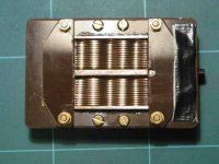
Here is a picture of the first transducer i did using hand drawn traces.
we are talking of adhesive-less laminates as thin as humanly possible!
I found things just got better the thinner[lighter] things went but that not the whole story.
All my parts were custom, nothing off the shelf.
I sort of got to the stage that to go further I would need to start to spend quite a bit more $$$$ to make things the way i wanted.
Here is a picture of the first transducer i did using hand drawn traces.
Attachments
I've done some toner-transfer printing - I assume that making and etching a set of traces should be pretty simple. However, I've had no luck finding a potential source of laminate. How did you make (or buy) yours, and how did you pleat it?
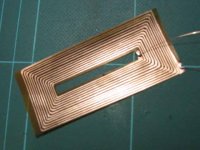
Also, I note a rather interesting and unusual magnet structure. Care to share details?
Also, I note a rather interesting and unusual magnet structure. Care to share details?
I drew the traces in the picture with a ruler and etch resist ink pen. The dc R came out about 4 Ohm a piece.
The later ribbon trace pattern was drawn up with pcb software.
did two versions of those one with around dc R of around 30 Ohm and one with around 15.
It has been a few years since i last worked on this project so details are not to hand,but sourcing the laminate was a bit of a headache , i was very lucky to get my samples!!
I will try to dig out some names etc
The pleats, or curves were added with a simple press former.
They key was to take out any tension on the ribbon.
This of course also relates to the ribbons own elastic characteristics..
The magnetic circuit is used was end poles pieces= North center pole piece =South.
The phones even with their flaws do sound nice and don't require anything excessive to drive them. [even sounded nice on my portable, all be it a bit quiet]
- Home
- Amplifiers
- Headphone Systems
- Ribbon or planar headphones