http://www.geocities.com/rjm003.geo/rjmaudio/diy_sze.html
I read the above link and thought that it would be nice if I could implement the circuit into a grounded cathode amplifier.
I don't have a working spice model for TINA SPICE, so I could not tell whether the whole circuit works or not. Theoretically, I think it'll work just fine, but I needed confirmation from you guys.")
The end of this post reveals the schematic.
I did not add any resistor values yet. I think the current schematic is sufficient to show how it'll operate. The values will be added once I have a positive feedback.
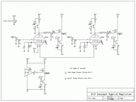
Tube stage:
1) 12FK6/12AE6 tubes running in grounded cathode mode. The tube is supplied by a regulated 24VDC supply. The cathode resistor is bypassed with a capacitor to increase gain.
2) Plate voltage will be set to 1/2 voltage supply, which is around 12V. This is achieved by tuning the trimpot.
3) The plate is loaded with a single BJT CCS, with LM336-2.0 voltage reference.
Output Stage:
1) 24VDC supply is split into +12V, -12V and a virtual ground using the TLE2426.
2) The output stage resembles the skezeres VE buffer I posted above, except the bias is done with an active CCS. The MOSFET used is an IRF150
3) Signal is AC coupled using a 0.1uF film capacitor from the tube stage. Using this method, I can avoid using large electrolytics and bypass film caps at the output. This interstage DC decoupling method is very similar to Cavalli Jone's SOHA amplifier.
4) Signal path for the headphone load is exactly the same as the rjm Skezeres VE amplifier. (ground is returned to the output of the "ground channel MOSFET)
Well, my question is pretty simple. Will this circuit work as intended?
I read the above link and thought that it would be nice if I could implement the circuit into a grounded cathode amplifier.
I don't have a working spice model for TINA SPICE, so I could not tell whether the whole circuit works or not. Theoretically, I think it'll work just fine, but I needed confirmation from you guys.
The end of this post reveals the schematic.
I did not add any resistor values yet. I think the current schematic is sufficient to show how it'll operate. The values will be added once I have a positive feedback.
Tube stage:
1) 12FK6/12AE6 tubes running in grounded cathode mode. The tube is supplied by a regulated 24VDC supply. The cathode resistor is bypassed with a capacitor to increase gain.
2) Plate voltage will be set to 1/2 voltage supply, which is around 12V. This is achieved by tuning the trimpot.
3) The plate is loaded with a single BJT CCS, with LM336-2.0 voltage reference.
Output Stage:
1) 24VDC supply is split into +12V, -12V and a virtual ground using the TLE2426.
2) The output stage resembles the skezeres VE buffer I posted above, except the bias is done with an active CCS. The MOSFET used is an IRF150
3) Signal is AC coupled using a 0.1uF film capacitor from the tube stage. Using this method, I can avoid using large electrolytics and bypass film caps at the output. This interstage DC decoupling method is very similar to Cavalli Jone's SOHA amplifier.
4) Signal path for the headphone load is exactly the same as the rjm Skezeres VE amplifier. (ground is returned to the output of the "ground channel MOSFET)
Well, my question is pretty simple. Will this circuit work as intended?
Attachments
looking at the RJMaudio link i posted, there was no "voltage divider" to bias the MOSFETS too.
Actually, the whole concept is just to use a tube preamp to drive the above mentioned MOSFET buffer.
I simulated the MOSFET buffer and it actually worked. I no expert, but please do let me know how to do it right lol.
Actually, the whole concept is just to use a tube preamp to drive the above mentioned MOSFET buffer.
I simulated the MOSFET buffer and it actually worked. I no expert, but please do let me know how to do it right lol.
Need something to bias the mosfet on. As it is the mosfet is turned off and it will not work.
Look at that schematic, again. The PSU is bipolar. Therefore, the gates are forward biased.
my PSU is ALSO Bipolar. I don't know if TLE2426 that chops the 24VDC into +12V -12V and ground also counts as a bipolar supply?
I suppose that it'll work theoretically?
Thanks, you guys are great.
EDIT: I was kinda confused too when jerluwoo told me there was no forward bias.
The 1Meg ground and -12V part will provide 12V of VGS bias for the MOSFETs right?
I suppose that it'll work theoretically?
Thanks, you guys are great.
EDIT: I was kinda confused too when jerluwoo told me there was no forward bias.
The 1Meg ground and -12V part will provide 12V of VGS bias for the MOSFETs right?
I order for the mosfet to be "on", the gate has to be 2-4 volts more positve than the source. If it is using the ccs to bias the mosfet then the output would be sitting somewhere around -3 volts instead of 0 volts. Can't use direct coupling this way and you run out of swing on the negative half before the positive half.
- Status
- This old topic is closed. If you want to reopen this topic, contact a moderator using the "Report Post" button.