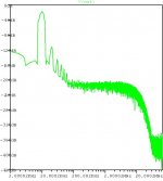
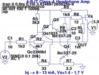
Here's the LTSpice schematic of a minimalistic discrete BJT low-power headphone amp, designed for 2.5 mW output into 32 ohms, using a single 3V power supply (2 x AAs are fine) with a quiescent current of 20 mA. The simulated THD20 is 0.003% at 2.5 mW into 32 ohms.
The output buffer topology is derived from this post by MikeB, based on a Class-A JFET voltage buffer topology from Steven:
http://www.diyaudio.com/forums/showthread.php?postid=1501336#post1501336
The rest of the circuit is a vanilla two-stage amplifier with voltage-series emitter-coupled feedback, with a closed-loop gain of ~4.
Attachments
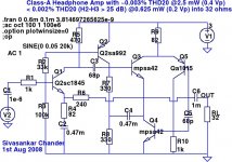
It's Class A, with a rated output swing of 400 mV into 32 ohms - so we need to be able to source and sink 12.5 mA. Adding some margin to avoid abrupt clipping as well as to operate the output devices at sweet spots, we get to 18 mA in the output devices and 2 mA elsewhere. I can't see how it's posible to go much lower than that in Class A.
20 mA from a 2.8 Ah alkaline AA gives 140 hours of operation, which is plenty.
20 mA from a 2.8 Ah alkaline AA gives 140 hours of operation, which is plenty.
20 mA x 2 = 40 mA
Even for operation with AA ( LR6 ) batteries
this is a bit much. So I agree Bonsai.
On the other hand, if we want Class A operation for 32 Ohm hphones,
I say that 18-20 mA can be a good choice.
Your circuit is interesting and I have saved a copy.
I would make another version. With regulated 12V supply.
I have made 2 such discrete 12 VDC headphones amplifiers for 32 Ohm.And I have published my schematics here at www.diyaudio.com This way you know that I have done some research and study of myself.
Good amplifier, you have. A bit too high current consumption.
Using rechargable LR6 (AA) would still not be too unconvinient to try.
> Using rechargable LR6 (AA) would still not be too unconvinient to try.
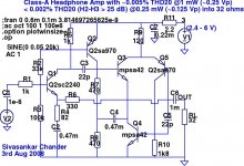
OK, I made a few biasing changes to allow operation with a 2.4 V rail, and reduced the output stage current as well. The tradeoff is that the output swing is now reduced to 250 mV only, limiting the output power to 1 mW into 32 ohms. (Headphones of sensitivity > 100 dB SPL / mW should be fine, but certain large can-type phones may not be sensitive enough for 1 mW drive.)
It will work with supplies of 2.4V to 6V and higher, and the THD20/sonics improve with higher rails. At 3V, the total quiescent current now simulates at ~14.5 mA, an improvement over the previous circuit. With 2 x 1.2V LR6/AA rechargeables, the quiescent current simulates at ~12.5 mA.
THD20 is more or less the same as the previous circuit, but sonics are slightly worse at full swing and 2.4 V rails. The closed-loop gain has been increased slightly to ~5.
Edit: R11 models the internal resistance of the battery for simulation. An optional small discrete resistance up to 10R can be placed in series with the battery for inrush current limiting, which will help to prolong the life of alkaline AAs. This can be omitted for NiMH AAs.
Attachments
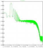
Looks pretty optimal:
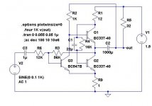
According to an old engineer's saying: "it's always possible to get the same results with half the parts or half the power", but in this case, I didn't quite succeed.
I did halve the parts and the power, but the distortion remains a dismal 0.017%.
Here is the circuit, but don't take it too seriously: it is just a joke, the product of intellectual masturbation.....
Attachments
That's indeed a clever minimalistic circuit. I can't seem to go much below 0.05% THD20 at full swings - but that's good enough for a minimal design that runs off a single AA.
I'm trying to optimize it (without much success) so that it works reasonably well with a variety of BJTs. In the sim, it looks like only the bc337 and 2sd669 work reasonably well as the lower (active load) device. Sonics are very sensitive to the resistor in the emitter legs.
I'm trying to optimize it (without much success) so that it works reasonably well with a variety of BJTs. In the sim, it looks like only the bc337 and 2sd669 work reasonably well as the lower (active load) device. Sonics are very sensitive to the resistor in the emitter legs.
Unlike yours, this circuit is not serious: a proper design must be immune to normal variations in the Hfe of transistors, etc, and battery operation must be possible from 0.9V to 1.6V per cell, which is certainly not the case here. It is mainly intended to check how far the limits can be pushed.
And if it can stimulate the creativity of someone else, so much the better.
And if it can stimulate the creativity of someone else, so much the better.
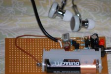
Here's a pic of the perfboard prototype (single channel only), just to verify the output stage concept. It seems to work much like the simulation, thus validating the concept of a saturating active load using a BC337-25. The phones are generic Chinese-made stethoscope-type in-ear buds stated to be 32 ohms.
I used Nichicon Muse SW and MV sub-miniature caps (bypassed by a film cap at the input), and a Rubycon YXG for the output DC blocking cap. When connected to an Ipod (3G), the bass is improved and there is more audible detail. However, there is some sibilance and other odd-harmonic artifacts, so it's a mixed bag overall, sonically. I believe the concept can be refined further, but the design space is heavily constrained by the 1.5V rail. Lots of things can be done with 3V, but at 3V one can just as well use a Maxim 9724/9725 and cut out the drudgery.
I used Nichicon Muse SW and MV sub-miniature caps (bypassed by a film cap at the input), and a Rubycon YXG for the output DC blocking cap. When connected to an Ipod (3G), the bass is improved and there is more audible detail. However, there is some sibilance and other odd-harmonic artifacts, so it's a mixed bag overall, sonically. I believe the concept can be refined further, but the design space is heavily constrained by the 1.5V rail. Lots of things can be done with 3V, but at 3V one can just as well use a Maxim 9724/9725 and cut out the drudgery.
Attachments
Nice work, linuxguru

I hope some more people here will try your circuit(s).
They are Perfect Diy Audio projects (if we do not want to go Blowtorch )
Good diyaudio, as being:
--- low cost
--- few parts
--- easy & clean (no mains hum) supply = battery
--- good hi-fi performance
Lineup
I hope some more people here will try your circuit(s).
They are Perfect Diy Audio projects (if we do not want to go
Blowtorch )Good diyaudio, as being:
--- low cost
--- few parts
--- easy & clean (no mains hum) supply = battery
--- good hi-fi performance
Lineup
Hi Lineup
I have just finished wavebournes little headphone amp and going to listen to it today and tomorow then i will let you know about the sound. Some minor tweaks to be tried too, then ill look at one more amp. Where can i view that circuit of yours which you plotted the harmonic spectrum for???
Linuxguru, nice looking circuit as usual, have you built this amp, what does it sound like??
Alex
homemodder
I think maybe you mean my BC368 BC369 output amplifier???
It is a complementary with 2SK170 / 2SJ74 input.
Uses low impedance current feedback!!!
The output is very powerful Class A (3+3 paralleled BC368/369) 100-120 mA idle PUSH-PULL (gives >200 mA current class a output)
It is one of the most interesting amplifiers I ever simulated/figured out.
Have not built it, yet.
Eventually you can try to replace the output
with one pair BD139 / BD140.
I do not think it would change very much of the performance.
Regards
I think maybe you mean my BC368 BC369 output amplifier???
It is a complementary with 2SK170 / 2SJ74 input.
Uses low impedance current feedback!!!
The output is very powerful Class A (3+3 paralleled BC368/369) 100-120 mA idle PUSH-PULL (gives >200 mA current class a output)
It is one of the most interesting amplifiers I ever simulated/figured out.
Have not built it, yet.
Eventually you can try to replace the output
with one pair BD139 / BD140.
I do not think it would change very much of the performance.
Complementary Class A Preamp using BC368-369
9th July 2008 .. by Lineup
http://www.diyaudio.com/forums/showthread.php?threadid=126100
Regards
Lineup, nice looking circuit too, very similar to cavali which I have built, from what I can remember it was a more simple design, having included a mosfet, jfet and bjt. On first listening I rate Wavebournes circuit better than the cavali but then again it has been some time since I listened to the cavali. Wavebournes was right, his circuit is powerfull enough to blow my eardrums with my HD600s. It completely blogs my girlfriends whineing away, very very good circuit wavebourne come up with.

I have a problem getting hold of 2sj74s, the shop I purchase parts from had 12000 pieces, sold all to someone about 3 weeks back, me thinking maybe a Mr Curl or Hansen. There is a race on for these jfets. Now they sitting with 17000 2sk170s and no complimentaries.
Alex
I have a problem getting hold of 2sj74s, the shop I purchase parts from had 12000 pieces, sold all to someone about 3 weeks back, me thinking maybe a Mr Curl or Hansen. There is a race on for these jfets. Now they sitting with 17000 2sk170s and no complimentaries.
Alex
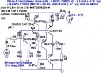
OK, back to our regularly scheduled programming - the 5-BJT topology on a 3V rail.
The latest version gets rid of the VAS capacitive bootstrap, and takes advantage of the fact that Vbe of Q4 stays fairly constant to get the collector load bootstrap for Q2 directly from the emitter of Q4. The closed-loop gain has been increased to ~10, and some biasing changes allow output swings of 300 mV. Quiescent current increases slightly to ~14 mA at 2.4V, and ~16 mA at 3V (still manageable). As before, it will work with a supply rail as low as 2.4V, but with increased distortion compared to 3V.
THD20 and sonics remain in the same ballpark. Here's the schematic (the layout has been changed to make the signal flow clearer and simpler):
Attachments
- Status
- This old topic is closed. If you want to reopen this topic, contact a moderator using the "Report Post" button.
- Home
- Amplifiers
- Headphone Systems
- Five-BJT low power headphone amp