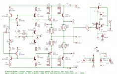
I've been toying around with a folded cascode amp, inspired by AD829, AD797 and LT1469. The aim is as usual portable use. I've come up with this simplified circuit. It simulates very well, seems robust (changing resistor values doesn't affect it that much), swings to within 1 V from rails, simulates well down to 3 V supply. R22/23 and R24 could be pots for trimming DC-offset and bias. 100 Ohms and 47 uF in series with the input simulates my iRiver IHP120.
Please comment.
Please comment.
An externally hosted image should be here but it was not working when we last tested it.
The three front end currents seem very low.
Is this to suit battery power?
You would probably be better using a FET input opamp for the front end if battery life is a concern.
How low can you take the output stage bias currents and still retain good crossover distortion suppression?
The 6p nested feedback cap looks unusual (can't read the number).
What about leaving alternative pads/traces/routes for other compensation strategies?
What Vbe is being predicted for the two folded cascodes?
Battery life is a concern, but not a major one. A cople of mA's more or less doesn't matter. What simulations should I run to find "proper" currents to the front stages? Increasing the currents doesn't alter the square wave response, phase response, voltage swing or distortion.
I don't really know how to detect crossover distortion but with a 30 Ohm load and 2.2 V output, I can see a slightly broken sine wave when the bias on the output transistors is 650 uA. With a 300 Ohm load, I can see no crossover distortion at any level. Please help me to learn how to measure or detect crossover distortion with LTSpice!
I'm just not clever enough to predict Vbe. I only know how to simulate. I usually try with different resistors, LED's, voltage supply etc to see to that there are some margins.
The two small (5 mA) capacitors are remnants from fiddling with the AD797 topology. They improve the sqaure wave, eliminating peaking without slowing it down like when the feedback capacitance is raised.
I'm done with monolithic opamps. There are some OK ones like AD797, AD829, AD8599, AD825, but even with my low level of electronic knowledge, I've made an all discrete amp that I find better.
Together with the 10 Ohm resistors, they reduce rail noise by a magnitude on the input stage. I doubt that it's audible though. I guess I could do it with a larger resistor and smaller capacitor, but I don't want to loose too much voltage swing.darkfenriz said:Looks nice to me.
100uF caps to ground seems a little overkill to me though")
Like this, AD829jam said:You might try replacing the Widlar current mirror with a Wilson mirror.
Jam
An externally hosted image should be here but it was not working when we last tested it.
or like this
An externally hosted image should be here but it was not working when we last tested it.
What improvents are expected? They simulate rather the same. If it's better, should I use it on the output stage as well?
I was hoping to keep the number of parts down since I inted it to fit inside a pocket sized box.
The red LED should have between 1.5 & 1.7V across it when lit.
You have only 0.3mA passing and I suspect this reduces the LED voltage and places it on a steep part of the IvsV curve.
What voltage is dropped across the LTP collector (load) resistors. I can't tell if they are 220r or 820r.
You have only 0.3mA passing and I suspect this reduces the LED voltage and places it on a steep part of the IvsV curve.
What voltage is dropped across the LTP collector (load) resistors. I can't tell if they are 220r or 820r.
Nelsonvandal,
Both circuits would work the first circuit which is the improved Wilson mirror is slightly better but might be overkill.
Q14 in the bottom circuit keeps the junction of Q14 from heating and unbalancing the mirror. I find it improves the performance of the mirror sonically ia an amplifier circuit I designed in another forum.
It might be worth a try on the output stage but I suspect it won't be as dramatic.
Good reading
http://users.ece.gatech.edu/~mleach/ece3050/su06/notes/bjtmirrsu06.pdf
If you are not a fan of feedback don't use this circuit.
Jam
The drop should be almost exactly 1 V. The resistors are 820 Ohm.AndrewT said:The red LED should have between 1.5 & 1.7V across it when lit.
You have only 0.3mA passing and I suspect this reduces the LED voltage and places it on a steep part of the IvsV curve.
What voltage is dropped across the LTP collector (load) resistors. I can't tell if they are 220r or 820r.
The current through the LED is 0.86 mA. Sorry about the crappy picture quality.
I'm glad you're willing to help. Where on the Scottish borders do you live? I've spent vacation in Coldstream a couple of years ago.
Thank you! I'll read it tonight, and probably do some simulating as well. I'm too old to learn elctronics the proper way, so I learn by soldering, simulating and reading this forumjam said:Nelsonvandal,
Both circuits would work the first circuit which is the improved Wilson mirror is slightly better but might be overkill.
Q14 in the bottom circuit keeps the junction of Q14 from heating and unbalancing the mirror. I find it improves the performance of the mirror sonically ia an amplifier circuit I designed in another forum.
It might be worth a try un the output stage but I suspect it won't be as dramatic.
Good reading
http://users.ece.gatech.edu/~mleach/ece3050/su06/notes/bjtmirrsu06.pdf
If you are not a fan of feedback don't use this circuit.
Jam
.
nelsonvandal said:
...Please comment.
Please include your LtSpice files as attchments in your posts:
Copy your .asc circuit file and rename the copy with .txt extension so diyAudio allows you to attach it to your post
then other LtSpice users can load it into their SwCad directory and re-rename with the .asc extension to run your exact circuit
helps with increasing the potential intelligence of the comments if we can quickly and easily run your circuits
device models that you've added to your sim can be added directly to a LtSpice .asc schematic that you want to share as "spice directives" -far right button on toolbar, just cut/paste the .model or .sub text into the box and drop it on the page - no need to mess with .inc/lib files
jam said:You might try replacing the Widlar current mirror with a Wilson mirror.
Jam
See ifyou can find BCV61... its good up to 30V...
Nordic,
Thanks for the tip. Might be the ticket fpr proper matching and thermal tracking........great idea!
http://www.nxp.com/acrobat_download/datasheets/BCV61_3.pdf
Complement is
http://www.nxp.com/acrobat_download/datasheets/BCV62_3.pdf
Jam
P.S. Now I have to learn how to use surface mount stuff........
Thanks for the tip. Might be the ticket fpr proper matching and thermal tracking........great idea!
http://www.nxp.com/acrobat_download/datasheets/BCV61_3.pdf
Complement is
http://www.nxp.com/acrobat_download/datasheets/BCV62_3.pdf
Jam
P.S. Now I have to learn how to use surface mount stuff........
Hi,
820r and half of 1.25mA gives 513mV.
Subtract this from LED volt of 1.6V and Vbe~=1V.
That is far too high.
The sim won't work properly.
But, if the LED drops only 513mV+600mV~=1100mV then the LTP works. But the LED @ 1100mV is seriously underbiased and will change voltage with the slightest changes in temperature and/or current and/or supply voltage.
You have to get the circuit working properly first before you think about analysing it's behaviour/performance.
I think I see what you mean. Can I just use a zener diode instead? What value would you recommend? I've read that a large voltage drop reduces noise but you lose some voltage swing, and voltage swing is more important when powered by batteries.AndrewT said:Hi,
820r and half of 1.25mA gives 513mV.
Subtract this from LED volt of 1.6V and Vbe~=1V.
That is far too high.
The sim won't work properly.
But, if the LED drops only 513mV+600mV~=1100mV then the LTP works. But the LED @ 1100mV is seriously underbiased and will change voltage with the slightest changes in temperature and/or current and/or supply voltage.
You have to get the circuit working properly first before you think about analysing it's behaviour/performance.
One alternative is to accept class AB and use 2 x 9 V batteries instead of 8 AAA cells.
I would also be happy if someone could recommend me "proper" currents to the front stages. After some reading, I understand that folded cascodes do better with some extra current. Since it's only driving the diamond buffer output stage, not the output transistors directly, do I really need more current? The problem is nothing "looks" better when simulating the circuit.
hi,
increase the voltage drop across the load resistors.
You can increase the resistor values and/or increase the LTP current.
FETs, I've heard, suit high current so how about asking others' advice about this solution.
Try increasing the LED current to 1mA and increase the Cascode current to around 1mA as well.
See how that stacks up with voltages around the circuit.
- Status
- This old topic is closed. If you want to reopen this topic, contact a moderator using the "Report Post" button.
- Home
- Amplifiers
- Headphone Systems
- Folded cascode headphone amp