Summary for those in a rush: I want to build a headphone/matrix mixer, how's the schematic look? Any suggestions?
I'm brand new to the boards, and what better way to kick things off than to dive right in, fully over my head. I've been practicing in a 6-person band in someone's basement for a while, and we really need to figure out a way to do individual headphone mixes. So my oh-so-ambitious project is to make a headphone mixer (aka monitor mixer, aka matrix mixer). I've looked around and found nothing in our budget (about 300-400) that satisfies my requirements, so I've started looking into building my own.
First, the requirements. We've got 6 people, 7 instruments (2x vocals, acoustic guitar, electric guitar, eletric bass, violin, drums). The drums are obviously the loudest, and right now we amp everything up to drum level and tune it back down with etymotic earplugs. Still, it's hard for everyone to hear themselves and hard to hear what each person is interested in, so we need a headphone mixer. 7 instruments mixed for 6 people, so I'm thinking a 7-input 6-output mixer (including either a drum overhead, or a room mic... haven't decided which yet).
I'm starting from this schematic and working forward.
Schematic taken straight from http://www.doepfer.de/DIY/a100_diy.htm
Obviously this is bare bones, and I don't expect professional mixer quality or results; just something functional, usable, not so noisy we hate it. I'm also trying to keep this cheap, under $100 if I can, which will probably balloon into $150 as I learn. My background is that I did computer engineering in college, took all the EE classes but mostly just worked with chips and FPGA's. I've done some soldering for fun, fixing computer parts and wiring things together. I don't mind soldering a bunch of opamps/pots/jacks together. That said, I've never tried anything nearly this ambitious.
So here's what I understand of the circuit. Each row in the circuit is basically an O-way (output) voltage divider. Each column is fed to a pair of unity gain inverting amplifiers, and then fed to the outputs. It looks like it can be expanded to any amount of inputs/outputs, with a pot at every junction.
I'm ready to order a huge amount of pots (7 input x 6 output = 42, plus 7 input gains and 6 output levels = 55 pots) and opamps, but I want to make sure of what I'm getting into here.
Some questions I have rolling around in my head:
We've got 2 mic inputs (typical cheap dynamic), 4 direct line-ins from amps, and one more mic (possibly condenser, preamped). Each output will be driving a pair of headphones of varying loads, probably pretty typical low-end closed/supra-aural headphones + IEM's. What should I expect as far as input levels/voltages? Should I count on adding buffers or preamps to the inputs? What kind of gain should I aim for at the output stages?
Why use two inverting opamps at each output stage? Why not just one non-inverting amp? I know it's probably a basic question, but I don't get it yet.
Is there any mods to the circuit you would suggest? I'm trying to keep the component count down since I'll be working with discrete components on perfboard or similar, and I'll be wiring everything by hand. Plus, every circuit will be multiplied by the amount of inputs/outputs, etc.
Any feedback, comments, criticisms, reality checks, etc is very much appreciated. I can't wait to start on this, especially if it works (it'll be such a godsend for our worn ears). Thanks so much!
I'm brand new to the boards, and what better way to kick things off than to dive right in, fully over my head. I've been practicing in a 6-person band in someone's basement for a while, and we really need to figure out a way to do individual headphone mixes. So my oh-so-ambitious project is to make a headphone mixer (aka monitor mixer, aka matrix mixer). I've looked around and found nothing in our budget (about 300-400) that satisfies my requirements, so I've started looking into building my own.
First, the requirements. We've got 6 people, 7 instruments (2x vocals, acoustic guitar, electric guitar, eletric bass, violin, drums). The drums are obviously the loudest, and right now we amp everything up to drum level and tune it back down with etymotic earplugs. Still, it's hard for everyone to hear themselves and hard to hear what each person is interested in, so we need a headphone mixer. 7 instruments mixed for 6 people, so I'm thinking a 7-input 6-output mixer (including either a drum overhead, or a room mic... haven't decided which yet).
I'm starting from this schematic and working forward.
An externally hosted image should be here but it was not working when we last tested it.
Schematic taken straight from http://www.doepfer.de/DIY/a100_diy.htm
Obviously this is bare bones, and I don't expect professional mixer quality or results; just something functional, usable, not so noisy we hate it. I'm also trying to keep this cheap, under $100 if I can, which will probably balloon into $150 as I learn. My background is that I did computer engineering in college, took all the EE classes but mostly just worked with chips and FPGA's. I've done some soldering for fun, fixing computer parts and wiring things together. I don't mind soldering a bunch of opamps/pots/jacks together. That said, I've never tried anything nearly this ambitious.
So here's what I understand of the circuit. Each row in the circuit is basically an O-way (output) voltage divider. Each column is fed to a pair of unity gain inverting amplifiers, and then fed to the outputs. It looks like it can be expanded to any amount of inputs/outputs, with a pot at every junction.
I'm ready to order a huge amount of pots (7 input x 6 output = 42, plus 7 input gains and 6 output levels = 55 pots) and opamps, but I want to make sure of what I'm getting into here.
Some questions I have rolling around in my head:
We've got 2 mic inputs (typical cheap dynamic), 4 direct line-ins from amps, and one more mic (possibly condenser, preamped). Each output will be driving a pair of headphones of varying loads, probably pretty typical low-end closed/supra-aural headphones + IEM's. What should I expect as far as input levels/voltages? Should I count on adding buffers or preamps to the inputs? What kind of gain should I aim for at the output stages?
Why use two inverting opamps at each output stage? Why not just one non-inverting amp? I know it's probably a basic question, but I don't get it yet.
Is there any mods to the circuit you would suggest? I'm trying to keep the component count down since I'll be working with discrete components on perfboard or similar, and I'll be wiring everything by hand. Plus, every circuit will be multiplied by the amount of inputs/outputs, etc.
Any feedback, comments, criticisms, reality checks, etc is very much appreciated. I can't wait to start on this, especially if it works (it'll be such a godsend for our worn ears). Thanks so much!
Attachments
My first post ...
The first op amp is set up as a virtual earth mixer. The second one probably provides the current capacity to drive headphones.
The first op amp uses the resistors down by each pot wiper, and its feedback resistor, to give you a combined signal. First point to make is that you should not build it as shown. Keep all the resistors as close as you can to the op amp terminals, otherwise it will probably be unstable.
I suggest that the input pots are about 100K lin, and the wiper resistors are 15K. That should prevent loading the sources (7 inputs in parallel on each one) and will give you a quasi-log control characteristic, see http://sound.westhost.com/project01.htm for the explanation.
Ideally, your first op amp should be followed by a volume control for the user, and the second op amp connected as a voltage follower, to give you a low output impedance to drive the headphones. It is possible to use the second op amp as shown, with the feedback resistor as your user volume control, but that is not recommended - any dirt on the track will result in no feedback signal, and a rail to rail squarewave in your ears.
There are several chips that can feed a headphone directly, and a design by Chu Moy on Headwise.com is about as simple as you can get. http://headwize.com/projects/showfile.php?file=cmoy2_prj.htm Since you are working from a mains supply, a discrete component design may be cheaper. Have a browse - there are plenty of designs there.
You will need some form of preamp on some of your inputs. The effects output of your guitar and bass amplfiers will probably give you about 1 v rms, and you will need to bring the microphones up to that level. If you choose not to use your guitar and bass preamps, you will need a buffer circuit of some description to stop the low input impedance sucking all the life from your sound. http://personalpages.tds.net/~fdeck/bass/quickand.pdf would be a possiblility.
A mixer with direct-outs on the microphone channels might be an easy option, but the alternative is to build microphone preamps. Since they are only for rehearsal use, you may get away with simplifying them to be unbalanced, but if not, there are circuits out there that will amplify a balanced micrphone. e.g. http://sound.westhost.com/project30a.htm.
Hope this helps.
Mottlefeeder, thanks so much for your feedback! It points out so many things that I had no clue about, and I'm already learning so much.
Here's my next iteration, incorporating a few changes from your suggestions.
First, I added an "input volume" to affect the trim/gain for that channel. Hopefully this will compensate for small variations in levels from the different instruments (assuming all instruments/mics are preamped).
Then I added the 100k linear pot + 15k trim. That link was great, I had no idea they cheaped out on the "audio" taper pots. Better for me anyway, linears will be cheaper and easier to find. I'm aiming at $.50 per pot right now, since those will most likely be the bulk of the cost of the mixer.
Next, I moved R2 closer to the opamp as opposed to right on near the mix pot. This will decrease instability for the opamp? I would ask why, but I'm sure it's been covered a bunch of times and I'll just have to read up on opamp instability. I'm assuming the distance is the problem, and wiring the resistors physically closer to the opamp is desireable.
Next, I added an output volume pot between the two opamps. Do I still need R3 in this case? Should I use the 100k linear + 15k trim for this too?
So now my questions (yeah more of them coming!):
If I keep all resistors (excluding the 15k) the same value, I think I'm looking at unity gain here. The default cmoy headphone amp seems to have a gain of about 11. Should I simply replace the second voltage following opamp with a cmoy headphone circuit? It seems that would simply be adding a couple of different value resistors and a cap. Or should I modify the first opamp to provide ~11 gain and use the second opamp as unity gain?
I have a mixer that I may be able to use as a multiple-channel mic preamp. If that's the case, then hopefully I shouldn't have to worry about the mic levels compared to the instrument levels. If that doesn't work, I'll need to do something simple for a mic preamp. My first instinct is to just use the unbalanced part of the balanced signal and put a simple inverting amplifier pair on the mic inputs; with some amount of gain on the first opamp and the second as a voltage follower (kinda like the output stage of from the original circuit). Anything wrong here? Like I said, hopefully my commercial mixer can be used to bring all levels up before it hits my circuit.
> any dirt on the track will result in no feedback signal, and a rail to rail squarewave in your ears.
Good point, I hadn't thought about that. My reasoning before was that if I put the pot in the feedback, it'll change the gain of the circuit and the noise level will be proportional to the gain. The alternative is to amp everything up to a certain maximum gain (with maximum noise), and attenuate the volume down, so the signal:noise ratio would always be at max. However, I'll take safety over less noise though, as I don't want to shoot out anyone's eardrums... especially mine if I'm using IEM's. So with the new way, if there's dirt on the tracks the circuit will simply cut out volume, right? Anywhere else I should worry about things like this?
I really do appreciate this feedback, I'm still very excited about the project and can't wait to see it start to form.
PS. Is there a simple free circuit drawing program I could use? I'm using Gimp right now, not the most efficient thing to use I'm sure.
Here's my next iteration, incorporating a few changes from your suggestions.
An externally hosted image should be here but it was not working when we last tested it.
First, I added an "input volume" to affect the trim/gain for that channel. Hopefully this will compensate for small variations in levels from the different instruments (assuming all instruments/mics are preamped).
Then I added the 100k linear pot + 15k trim. That link was great, I had no idea they cheaped out on the "audio" taper pots. Better for me anyway, linears will be cheaper and easier to find. I'm aiming at $.50 per pot right now, since those will most likely be the bulk of the cost of the mixer.
Next, I moved R2 closer to the opamp as opposed to right on near the mix pot. This will decrease instability for the opamp? I would ask why, but I'm sure it's been covered a bunch of times and I'll just have to read up on opamp instability. I'm assuming the distance is the problem, and wiring the resistors physically closer to the opamp is desireable.
Next, I added an output volume pot between the two opamps. Do I still need R3 in this case? Should I use the 100k linear + 15k trim for this too?
So now my questions (yeah more of them coming!):
If I keep all resistors (excluding the 15k) the same value, I think I'm looking at unity gain here. The default cmoy headphone amp seems to have a gain of about 11. Should I simply replace the second voltage following opamp with a cmoy headphone circuit? It seems that would simply be adding a couple of different value resistors and a cap. Or should I modify the first opamp to provide ~11 gain and use the second opamp as unity gain?
I have a mixer that I may be able to use as a multiple-channel mic preamp. If that's the case, then hopefully I shouldn't have to worry about the mic levels compared to the instrument levels. If that doesn't work, I'll need to do something simple for a mic preamp. My first instinct is to just use the unbalanced part of the balanced signal and put a simple inverting amplifier pair on the mic inputs; with some amount of gain on the first opamp and the second as a voltage follower (kinda like the output stage of from the original circuit). Anything wrong here? Like I said, hopefully my commercial mixer can be used to bring all levels up before it hits my circuit.
> any dirt on the track will result in no feedback signal, and a rail to rail squarewave in your ears.
Good point, I hadn't thought about that. My reasoning before was that if I put the pot in the feedback, it'll change the gain of the circuit and the noise level will be proportional to the gain. The alternative is to amp everything up to a certain maximum gain (with maximum noise), and attenuate the volume down, so the signal:noise ratio would always be at max. However, I'll take safety over less noise though, as I don't want to shoot out anyone's eardrums... especially mine if I'm using IEM's. So with the new way, if there's dirt on the tracks the circuit will simply cut out volume, right? Anywhere else I should worry about things like this?
I really do appreciate this feedback, I'm still very excited about the project and can't wait to see it start to form.
PS. Is there a simple free circuit drawing program I could use? I'm using Gimp right now, not the most efficient thing to use I'm sure.
Having a sensitivity control and a mix control is necessary on a quality mixer with aux sends etc, but here, you could manage without the 'input volume'. Use the 100K pot as the combined input gain and mix control. Incidentally, once set, these controls will not be moved that often so you could economise and use trimmer pots with built-in spindles here.Originally posted by jumpfroggy
First, I added an "input volume" to affect the trim/gain for that channel. Hopefully this will compensate for small variations in levels from the different instruments (assuming all instruments/mics are preamped).
You don't need the 15K resistor here, you can use R2 = 15K. See next comment.Originally posted by jumpfroggy
Then I added the 100k linear pot + 15k trim. That link was great, I had no idea they cheaped out on the "audio" taper pots. Better for me anyway, linears will be cheaper and easier to find. I'm aiming at $.50 per pot right now, since those will most likely be the bulk of the cost of the mixer.
The op amp sees a current at its -ve input, and drives the output up (or down) until the current coming back through the feedback resistor is equal and opposite, so the two currents cancel out and the -ve input pin is held at zero volts and zero current. This means -Originally posted by jumpfroggy
Next, I moved R2 closer to the opamp as opposed to right on near the mix pot. This will decrease instability for the opamp? I would ask why, but I'm sure it's been covered a bunch of times and I'll just have to read up on opamp instability. I'm assuming the distance is the problem, and wiring the resistors physically closer to the opamp is desireable.
(a) for all practical purposes, you can assume R2 is connected between the pot wiper and ground, and
(b) any interference appearing at the -ve input is going to destroy that balance of current, so all resistors etc associated with the feedback loop should be as close to the chip as possible.
You still need R3 and the feedback resistor to define the gain, but yes you could use 100K linear & R3 = 15K as above.Originally posted by jumpfroggy
Next, I added an output volume pot between the two opamps. Do I still need R3 in this case? Should I use the 100k linear + 15k trim for this too?
Many op amps work well at a gain of about 10, and need special care with gains below that because they tend to be unstable. The easy option is to give each op amp a gain of about 10, and lose the extra gain in the potentiometers. With log pots, it is only a fraction of a turn.Originally posted by jumpfroggy
If I keep all resistors (excluding the 15k) the same value, I think I'm looking at unity gain here. The default cmoy headphone amp seems to have a gain of about 11. Should I simply replace the second voltage following opamp with a cmoy headphone circuit? It seems that would simply be adding a couple of different value resistors and a cap. Or should I modify the first opamp to provide ~11 gain and use the second opamp as unity gain?
Assuming your microphones are lo-Z (600 ohms) this op amp configuration should work. Amplifying a hi-Z microphone (50K) will probably need a different configuration of op amp circuit so that you do not have a low value resistor (R2 or R3 in your circuit) connected to the microphone (and shunting it to virtual ground)Originally posted by jumpfroggy
I have a mixer that I may be able to use as a multiple-channel mic preamp. If that's the case, then hopefully I shouldn't have to worry about the mic levels compared to the instrument levels. If that doesn't work, I'll need to do something simple for a mic preamp. My first instinct is to just use the unbalanced part of the balanced signal and put a simple inverting amplifier pair on the mic inputs; with some amount of gain on the first opamp and the second as a voltage follower (kinda like the output stage of from the original circuit). Anything wrong here? Like I said, hopefully my commercial mixer can be used to bring all levels up before it hits my circuit.
By the way, we haven't mentioned it so far, but your circuit is DC coupled from input to output. This works in theory, but in practice you would be better with capacitors in-line somewhere, possibly between the input sockets and the tracks of the potentiometers.
You're right, the sensitivity really shouldn't be necessary, since hopefully levels will be relatively close when coming in. I should probably leave it out for this project. I was reading some document about getting all the sensitivities right and then starting with all pots straight up, but that's probably overkill for this project.Originally posted by Mottlefeeder
Having a sensitivity control and a mix control is necessary on a quality mixer with aux sends etc, but here, you could manage without the 'input volume'. Use the 100K pot as the combined input gain and mix control.
Our setup will likely change every once in a while (amps, mics, etc), and I imagine each person will be tweaking the values during practice quite a bit till it gets settled down. I envision each person can run up to the board while we're playing, change the level they want, and then jump back in.Originally posted by Mottlefeeder
Incidentally, once set, these controls will not be moved that often so you could economise and use trimmer pots with built-in spindles here.
Most trims I've seen are small, no spindle (that's the "handle" part, right?) and hard to set. What's the difference between a trim w/ spindle and a normal pot? I've found a really cheap $.20 100k linear pot at allelectronics.com, cheapest I've found yet.
Took me a while, but I had a little epiphany, and it all makes sense now. The opamp is wired to always push back to 0 on the negative input, and so the output simply reflects the negative feedback. Since you're running the negative feedback through a resistor, that means only a portion of the output signal is feeding back; if 1/10 of the output is going back as negative feedback, then the output will be -10x the input. Makes sense now.Originally posted by Mottlefeeder
You don't need the 15K resistor here, you can use R2 = 15K. See next comment.
The op amp sees a current at its -ve input, and drives the output up (or down) until the current coming back through the feedback resistor is equal and opposite, so the two currents cancel out and the -ve input pin is held at zero volts and zero current. This means -
(a) for all practical purposes, you can assume R2 is connected between the pot wiper and ground, and
(b) any interference appearing at the -ve input is going to destroy that balance of current, so all resistors etc associated with the feedback loop should be as close to the chip as possible.
I remember now reading that some opamps were good choices for the CMOY since they were unity stable, which made them easier to work with. If I just put each opamp at about 10 gain, then overall the circuit would be 20 gain and I'd just attenuate down with the volume. Does that sound right?Originally posted by Mottlefeeder
You still need R3 and the feedback resistor to define the gain, but yes you could use 100K linear & R3 = 15K as above.
Many op amps work well at a gain of about 10, and need special care with gains below that because they tend to be unstable. The easy option is to give each op amp a gain of about 10, and lose the extra gain in the potentiometers. With log pots, it is only a fraction of a turn.
I'll ignore mic levels for now, and just use external preamps. If I can't do that, I'll think about the mic preamps later.Originally posted by Mottlefeeder
Assuming your microphones are lo-Z (600 ohms) this op amp configuration should work. Amplifying a hi-Z microphone (50K) will probably need a different configuration of op amp circuit so that you do not have a low value resistor (R2 or R3 in your circuit) connected to the microphone (and shunting it to virtual ground)
By the way, we haven't mentioned it so far, but your circuit is DC coupled from input to output. This works in theory, but in practice you would be better with capacitors in-line somewhere, possibly between the input sockets and the tracks of the potentiometers.
I added C1 on each input. What kind of value would I look at for this? I always figured these were low-value high-pass filters, never thought about DC current. Is this mainly a safeguard for transient situations (plugging in mic, etc), or are there likely to be persistent dc currents for some reason?
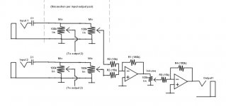
Ok, here it is:
An externally hosted image should be here but it was not working when we last tested it.
I added the caps to the input to eliminate DC, unknown value so far.
I've added a second input to show how the inputs/outputs will be wired, matrix style.
R2 is duplicated for each input/output pair.
I set R1 and R4 to 150k, since that will give a gain of 150k/15k = 10. That right?
It's amazing, I can look at circuits I saw before all this discussion, and I understand so much more of it. I actually get the CMOY now! I feel just about ready to start ordering parts, just waiting for the final shakedown to make sure I'm not getting too much/too little of each piece.
Attachments
Trim pots are not designed for frequent use, and will wear away the track faster. Some trim pots offer a shaft which clips in as an optional extra, like this one. http://www.farnell.com/datasheets/18182.pdf. Your proposed pot is cheaper because it has no mounting bush - good call if you pcb mount, bad call if you want to panel mount.Originally posted by jumpfroggy
Most trims I've seen are small, no spindle (that's the "handle" part, right?) and hard to set. What's the difference between a trim w/ spindle and a normal pot? I've found a really cheap $.20 100k linear pot at allelectronics.com, cheapest I've found yet.
Almost - the maximum gain will be 10 X 10 not 10 + 10Originally posted by jumpfroggy
I remember now reading that some opamps were good choices for the CMOY since they were unity stable, which made them easier to work with. If I just put each opamp at about 10 gain, then overall the circuit would be 20 gain and I'd just attenuate down with the volume. Does that sound right?
It is possible that you could have a dc offset on your incoming signal - better safe than sorry.Originally posted by jumpfroggy
I added C1 on each input. What kind of value would I look at for this? I always figured these were low-value high-pass filters, never thought about DC current. Is this mainly a safeguard for transient situations (plugging in mic, etc), or are there likely to be persistent dc currents for some reason?
C1 works with the input impedance to give you a high pass filter. Your worst case input impedance is when all the pots on that channel are at max, so the input signal will see 7 X 15K in parallel, which is about 2K. From that you can calculate (or look-up) a value for C based on a 30Hz -3dB cutoff point.
That would be my starting point. You will also need to add capacitors across the supply pins of each chip, and think about layouts to minimise crosstalk etc. - standard good design stuff you can see in other peoples' designs.Originally posted by jumpfroggy
Ok, here it is:
An externally hosted image should be here but it was not working when we last tested it.
I added the caps to the input to eliminate DC, unknown value so far.
I've added a second input to show how the inputs/outputs will be wired, matrix style.
R2 is duplicated for each input/output pair.
I set R1 and R4 to 150k, since that will give a gain of 150k/15k = 10. That right?
That's about as far as I can take you without starting to build it myself - have fun
- Status
- This old topic is closed. If you want to reopen this topic, contact a moderator using the "Report Post" button.