A few months ago Ozgur Okolay prompted me to purchasing a new set of head phones and it followed to designing a few head phone amps using different topologies to establish which sound I could live with for prolonged periods.
I like listening to my jazz collection while working and having a set of headphone on my head for 8 - 10 hours a day is quite normal.
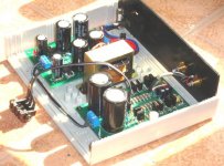
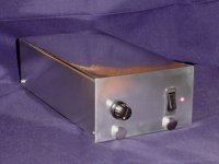
Jacco Vermeulen mentioned it in another thread and this prompted me to start a thread sharing the simple SE class A that I have been using for the past three weeks.
I am using it with a pair of Sennheizer HD650's and it is powered from a regulated +-10V PSU.
Some may say that the design is not a sophisticated enough to present here but it does sound very realistic and I do not suffer from any fatgue at all.
I will publish the other topologies I made which includes a full complementary symetry and a valve mosfet hybrid should anyone be interested.
I like listening to my jazz collection while working and having a set of headphone on my head for 8 - 10 hours a day is quite normal.
Jacco Vermeulen mentioned it in another thread and this prompted me to start a thread sharing the simple SE class A that I have been using for the past three weeks.
I am using it with a pair of Sennheizer HD650's and it is powered from a regulated +-10V PSU.
Some may say that the design is not a sophisticated enough to present here but it does sound very realistic and I do not suffer from any fatgue at all.
I will publish the other topologies I made which includes a full complementary symetry and a valve mosfet hybrid should anyone be interested.
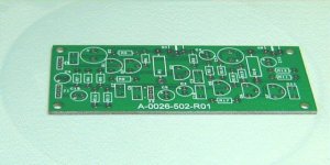
Attachments
There is a lot to be said for keeping things simple. Having said that, have you tried a CCS loaded output compared to the resistor loaded version as in your schematic? If so, is there a marked difference in real-world results?
I am going to build a headphone amp soon, so I would be interested in viewing your other circuits too.
As an aside, it's also worthwhile mentioning for any beginners reading that this type of circuit can work as a useful line stage with just the addition of a volume control (and not forgetting a decent power supply!)
I decided to present the amp in its most basic form and invite anyone to contribute and turn it into a useful amplifier for those head-fi enthusiasts.
There are several improvements to be made, to the basic design that I have already experimented with and introduced but it is always good to see what others can bring to the table and take it from there.
This project is intended to be inexpensive and appeal to beginners as well as anyone who would care to join in.
I will be quite happy to do printed circuit diagrams, etc.
Interestingly, many may say that head phone listening is not hi-fi, but being an audio fanatic for >35 years, my eyes or is it ears opened when I started my research some months ago. There are much more to head phone listening than meets the eye or is it ear.
There are many factors that influence what and how the material we hear is perceived and processed that is totally different from listening to speakers in a room with its own accoustic character.
Moreover, signals heard with speakers are reflected, attenuated, delayed, mixed, etc. all contributing to how we perceive the signal and enjoy or hate what we hear.
Headphone reveal the hidden qualities in recordings that I have never experienced with a standard set-up of any quality and in any envirnment.
In the past, listening to head phones was something I did when my wife irritated me or I got annoyed wth the background noise.
Many think that you plug in a set of headphones into your standard amp and that is what head phone listening is all about.
Wrong, most amps are made to drive loudspeakers at considerable power, the distortions at low power is easily heard on head phone, because only a few mW is needed.
Most class AB amplifiers cross-over distortion at this low power level exceeds the power needed to drive the headphones loud.
Some power amps generates more noise and hum than loud listening levels on head phones.
Get this all right in a headphone amp and you will realise what you have been missing all your audio life.
Hi Gordy, thanks for your comment. I will publish the other designs as well but would like to create a group design and achieve more than just publishing what I think is good.
You are absolutely right, good audio starts with a solid power supply, there are no alternatives. Whether it is mains powered or battery powered. Noise is probably the most important factor.
You are absolutely right, good audio starts with a solid power supply, there are no alternatives. Whether it is mains powered or battery powered. Noise is probably the most important factor.
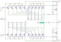
Here is the second head phone amp circuit that may be up for discussion, it is a symetrical complimentary topology with a difference. The parallel transistors have an added benefit, the sum of the non-coherent noise current results in 7 dB reduction in noise vs a single long tail pair.
Although it uses more components it is still a simple design.
This amplifier does not sound better or worse than the first, it sounds different. The noise is quite a bit lower because even pushing the head phones hard onto your ears reveals total silence.
The noise is still further improved by using power transistors (BD139/140) due to their larger junctions compared to small signal devices.
Attachments
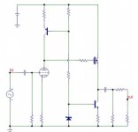
Finaly there is a hybrid low voltage tube design. The idea is borrowed from another circuit that I have received from another forum member DXaudio by e-mail a year or so ago. This circuit does provide the "typical" valve sound but without the limitations of an output transformer.
Attachments
Gordy said:There is a lot to be said for keeping things simple. Having said that, have you tried a CCS loaded output compared to the resistor loaded version as in your schematic? If so, is there a marked difference in real-world results?
I am going to build a headphone amp soon, so I would be interested in viewing your other circuits too.
As an aside, it's also worthwhile mentioning for any beginners reading that this type of circuit can work as a useful line stage with just the addition of a volume control (and not forgetting a decent power supply!)
Gordy, the first improvement to the is amp is using a CCS, I used a LM317 in my current version.
One can also use the classic resistor zener CCS but I find this adds much hiss and is very anoying at low volumes, so I suggest either a mosfet or LM317.
I kinda like the LM317 CSS for valve headphone amps.
I feel it fits in better with the sound carracter of single valve/hybrid headphone amps...
I'm just so bussy, not evem had a chance to start up my new soldering station I bought early in the week...
I feel like a crack merchant, just filling up bags all day long for days on end.
I feel it fits in better with the sound carracter of single valve/hybrid headphone amps...
I'm just so bussy, not evem had a chance to start up my new soldering station I bought early in the week...
I feel like a crack merchant, just filling up bags all day long for days on end.
Howzit Nordic, I know the feeling, as long as it is bags of money you refer to. I have just completed wiring in a back-up power system to all the things that I need in case of power failures..
We are getting ready for what you had and probably still have in CT. At least here we get a time table with power outages per area
Turned the system on and wow, no smoke, sparks or anything in the house going live.
We are getting ready for what you had and probably still have in CT. At least here we get a time table with power outages per area
Turned the system on and wow, no smoke, sparks or anything in the house going live.
Nico Ras said:
Gordy, the first improvement to the is amp is using a CCS, I used a LM317 in my current version.
One can also use the classic resistor zener CCS but I find this adds much hiss and is very anoying at low volumes, so I suggest either a mosfet or LM317.
I like the simplicity of the 317, and it fits into the sentiment of the project too.
You may already have the following info on Constant Current Sources... well worth a read...
http://www.audioxpress.com/magsdirx/ax/addenda/media/jung2778.pdf
and
http://www.audioxpress.com/magsdirx/ax/addenda/media/jung2779.pdf
Gordy said:
I like the simplicity of the 317, and it fits into the sentiment of the project too.
You may already have the following info on Constant Current Sources... well worth a read...
Hi Gordy,
I have made several measurements and it appears as if the distortion with a resistive load is an order of magenetude lower than using any typical CCS.
Unless someone can advise otherwise I suggest that the circuit should remain as in 1.
The measurements where taken at 4V p-p into a 50 Ohm resitive load.
- Status
- This old topic is closed. If you want to reopen this topic, contact a moderator using the "Report Post" button.
- Home
- Amplifiers
- Headphone Systems
- Simple Headphone Amp