Without much further ado, here are the details of the full mod for the KSA-5 clone.
Note that despite simplicity, it is not a mod for (complete) beginners. I have had no issues and good repeatability, but I only modified two channels. You may experience issues that will require an oscilloscope, a signal generator, and some experience to resolve. But then again, you may get away with it")
The list of changes to the original schematic:
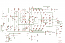
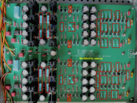
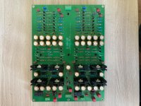
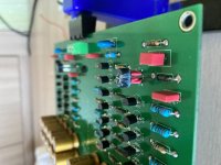
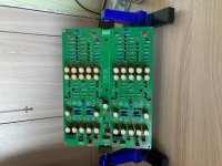
The schematic with modifications is attached. Since resistors's names are not marked on the board, I also attach a photo showing what to replace with what. Note that the additional parts from step 12 above are not shown - they are under the PCB.
The list of parts required to modify two channels:
With power on, check the output for a possible oscillation, then adjust the bias and re-check for oscillations. The quiescent current needs to be at about 20mA per transistor - with 0.22 ohm emitter resistors, it corresponds to 4mV between the test points, which should be easy to measure with a DVM. Higher bias levels are possible, but the distortion will be slightly higher. If you have a decent sound card and an appropriate software, you can trim the bias for the best distortion.
Let the amplifier warm up for 10-15 minutes and readjust the bias.
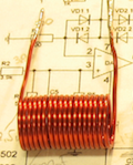
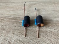
As with any feedback amplifier, capacitive loads may affect stability. In my testing, the amplifier remained stable with capacitive loads of up to 100nF, although with a smaller phase margin . Consider adding the usual RL network between the output of each channel and the load to ensure stability. Make 20-30 turns of 18 AWG single core insulated wire on a 1/2 inch (12mm) former - a Sharpie will work - to make an air core inductor (see the attached photo for an example), then connect a 10ohm 2-3W resistor in parallel to it.
Note that despite simplicity, it is not a mod for (complete) beginners. I have had no issues and good repeatability, but I only modified two channels. You may experience issues that will require an oscilloscope, a signal generator, and some experience to resolve. But then again, you may get away with it
The list of changes to the original schematic:
- Replace R1, R2, R6, R7 with 100 ohm resistors
- Replace R5 and R8 with 332 ohm resistors
- Replace R9, R10, R11, R12 with 274 ohm resistors
- Replace R16 and R17 with 22 ohm resistors
- Replace R19 with a 562 ohm resistor (reuse one of R5/R8)
- Replace R23 with a 1 Megohm resistor
- Replace R24 with a 68pF 50V NP0/C0G ceramic capacitor
- Replace R33, R34, R35 and R36 with 0.22 ohm 2W or 3W resistors
- Replace R37 and R38 with one 47 ohm resistor connected between bases of Q23/Q24 and Q25/26. Make sure to connect the new resistor correctly - see the build guide below - or your output transistors are at risk.
- Replace R47 with a 3.92k resistor
- Remove C2 and C3
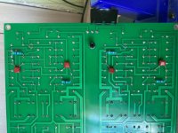
- Add a 4.7nF film capacitor and a 47 ohm resistor, connected in series, between the collectors of Q2 and Q3. Add another 4.7nF film capacitor and a 47 ohm resistor, also connected in series, between the collectors of Q7 and Q8. Place the new parts on the underside of the board if you like.
The schematic with modifications is attached. Since resistors's names are not marked on the board, I also attach a photo showing what to replace with what. Note that the additional parts from step 12 above are not shown - they are under the PCB.
The list of parts required to modify two channels:
- 8x 0.22 ohm 2W or 3W resistors
- 4x 22 ohm resistors
- 6x 47 ohm resistors
- 8x 100 ohm resistors
- 8x 274 ohm resistors
- 4x 332 ohm resistors
- 2x 562 ohm resistors (not needed if you can reuse R5/R8)
- 2x 3.92k resistors
- 2x 1 Megohm resistors
- 2x 68pF 50V capacitors, NP0/C0G ceramic
- 4x 4.7nF film capacitors
- Some 18 AWG single core insulated wire and 2x 10 ohm 2-3W resistors for the output RL network
With power on, check the output for a possible oscillation, then adjust the bias and re-check for oscillations. The quiescent current needs to be at about 20mA per transistor - with 0.22 ohm emitter resistors, it corresponds to 4mV between the test points, which should be easy to measure with a DVM. Higher bias levels are possible, but the distortion will be slightly higher. If you have a decent sound card and an appropriate software, you can trim the bias for the best distortion.
Let the amplifier warm up for 10-15 minutes and readjust the bias.
As with any feedback amplifier, capacitive loads may affect stability. In my testing, the amplifier remained stable with capacitive loads of up to 100nF, although with a smaller phase margin . Consider adding the usual RL network between the output of each channel and the load to ensure stability. Make 20-30 turns of 18 AWG single core insulated wire on a 1/2 inch (12mm) former - a Sharpie will work - to make an air core inductor (see the attached photo for an example), then connect a 10ohm 2-3W resistor in parallel to it.
Attachments
Last edited:
In this use case, you probably don’t need to modify the output stage (i.e. change the emitter resistors and re-adjust the bias), as it has a very, very easy job to do. Still, boosting the loop gain will improve the linearity of the amp.I use KSA5 as a pre-amplifier for a power amplifier with an input impedance of 10k
That depends on how you bias it. The original was apparently dissipating about 10W for two channels at idle. If modified as described above, the idle dissipation will be about 3.5W for two channels.hi guys, what is the power draw (watts) of the ksa5 ?
alexcp hello. I would like to finally decide for myself whether it is worth remaking the amplifier according to your recommendation or leaving it as it is? Use as a pre-amplifier for a power amplifier, with the possibility of a separate output (there is a switch) in the future for 32-ohm headphones.

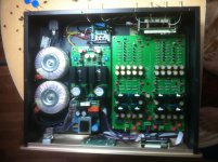
Hello. I upgraded the amplifier on a green board from Kevin Gilmour (as recommended alexcp) and compared it with the big black Chinese road (the circuits are the same). There are differences, but so far they are insignificant (I compare them on headphones, hereinafter as preliminary). The fact that now it is not heated like an iron is a big plus. After 2 hours of wiretapping, the preference, of course, is a reworked one. But I have a relay volume control on one (which I redone), and on the other amplifier there is ALPS.
Attachments
Meaning two KSA-5 channels driving one load in BTL configuration? It should be possible - just add a phase splitter. But IMO a balanced version of KSA-5 would need to be designed a little differently.Any thoughts of making a balanced version of this amp?
There was a discussion of the balanced version on Head-Case, right from the start of the thread:
Somebody there eventually (in 2018) reported that he was building a balanced KSA-5 but that it was more difficult and expensive to make than expected. No photos or schematics were posted AFAIK.kevin gilmore said:Single ended not really a HE6 killer, but balanced, a HE6 heavyweight for sure.
single ended with +/-21 power supplies, it does 10 vrms into 4 ohms or more.
balanced 20 vrms into 8 ohms or more.
single ended with +/-35 power supplies, it does 16 vrms into 4 ohms or more.
balanced 32 vrms into 8 ohms or more.
Just finished mine up a bit ago, I've had it breaking in on a table for a week, but did the signal wiring this evening and I couldn't be happier. I have no idea what it sounds like without alexcp's mods, but I am extremely pleased right now, this sounds fantastic. Thanks alexcp!


- Home
- Amplifiers
- Headphone Systems
- Krell KSA5