Just recently I've made some measurements on headphone amplifiers driving low-impedance headphones. I thought that sharing some of the results could be of interest here.
The headphone amp on test is my quite old design for Creek Audio - OBH11SE revision "B", incorporating very linear discrete class A circuit. It has two output sockets with different series resistors - one with 22 Ohm and second with 47 Ohm. The effect I am going to demonstrate exists on all headphones I've tried, however with low-impedance Grado SR-60 it is very strong.
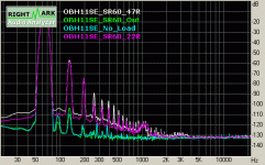
The link below shows the results of 4 tests - for the amp only, for the amp output driving Grados - signal taken BEFORE the resistor on the output, than after the resistor for 22 and 47 Ohm values. The test frequency (65 Hz) was chosen to show the effect clearly - the extended harmonics from the headphones (not from the amp!) clearly dominate the graph. Output voltage of the amplifier was the same in all tests - 1.28V RMS for THD measurements (however the voltage on the headphones was different for 22 and 47 Ohm resistors - for 22 it was almost 6 dB more) . I've normalized the levels for the RMAA test to work.
Here is the link with full results:
http://www.ant-audio.co.uk/Data/Resistor_Effect.htm
and I attach here one picture
Cheers
Alex
Attachments
I notice the 2nd is much lower on the 3 KHz signal in the intermod test so this appears to be a low frequency phenom
of course many nonlinear distortion factors are displacement related which increases for low frequency
loudspeaker dynamic driver nonlinear modeling might be a helpful guide although perhaps smaller headphone drivers may have somewhat different ordering of distortion mechanisms:
http://klippel.de/pubs/Klippel papers/Loudspeaker Nonlinearities–Causes,Parameters,Symptoms_06.pdf
All of the motor and mechanical non-linearities are reflected into the primary of the driver. If you drive it from a voltage source the zero impedance drive forces the terminal voltage to have low distortion. However, the distortion can be seen in the current waveform and when you drive it from a higher impedance source the driver impedance forms a non-linear voltage divider. The distortion should be level dependent, and should increase with decreasing frequency with constant voltage drive assuming simple motor behavior. High second order products indicates that they did not do much to provide a symmetrical motor.
Pete B.
Pete B.
The latest edition of Hi-Fi News has a technical review of some reasonable quality headphones with measurements.
It is amazing how the often used series resistor in the headphone socket alters the headhpone response. Looking at your findings x-pro, I think th e case is clear for headphones being driven by a good quality amp with no series resistor . . . .
It is amazing how the often used series resistor in the headphone socket alters the headhpone response. Looking at your findings x-pro, I think th e case is clear for headphones being driven by a good quality amp with no series resistor . . . .
I will soon be designing a headphone amp for my home system and I found your results very interesting, thanks for posting.
I use a couple of Creek parts in the system in my study so maybe I have your design in my home already!
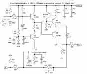
I do not wish to infringe IP, however if the OBH11SE revision "B" is an older design perhaps you could post the schematic for reference? Or perhaps the schematic with the values blanked out?
Regards,
G.
Gordy said:if the OBH11SE revision "B" is an older design perhaps you could post the schematic for reference?
It is out of production for more than 5 years. Here is the main part of the circuit, omitting power supply, volume control, input and output arrangements. It is class A SE output, so the output devices require heatsinks.
Cheers
Alex
Attachments
- Status
- This old topic is closed. If you want to reopen this topic, contact a moderator using the "Report Post" button.
- Home
- Amplifiers
- Headphone Systems
- Headphone distortion

