Hi all,
I made a Class A headphone amp last week. Its based from originally headwize forum "A HeadWize Design Series Paper" article. "Class A MOSFET Follower" design.
I use OPA134 op-amp for the buffer and it has 2 gain.
When first try, I faced there was -4 v offset on outputs (there was no output capacitor) And I couldnt fix that problem with adjusting the offset trimmer. Then I decided to put a 1500uF cap on output. However its a bit disturbing. Because the original design has no output capacitor. (There is no offset on op-amps output)
Anybody has any idea?
Thanks a lot for replies in advance.
Best regards..
I made a Class A headphone amp last week. Its based from originally headwize forum "A HeadWize Design Series Paper" article. "Class A MOSFET Follower" design.
An externally hosted image should be here but it was not working when we last tested it.
I use OPA134 op-amp for the buffer and it has 2 gain.
When first try, I faced there was -4 v offset on outputs (there was no output capacitor) And I couldnt fix that problem with adjusting the offset trimmer. Then I decided to put a 1500uF cap on output. However its a bit disturbing. Because the original design has no output capacitor. (There is no offset on op-amps output)
Anybody has any idea?
Thanks a lot for replies in advance.
Best regards..

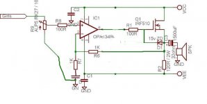
Could you provide the link to the original schematics? The circuit you've posted here should produce about -4V on the output as the o/p voltage of the opamp is near 0V and a MOSFET needs 4V to open. I suspect that in the original circuit there was a capacitor between the opamp and the MOSFET. On top of this the polarity of the output electrolytics on your diagram is wrong.
Cheers
Alex
P.S. - I've attached a modded picture to show where the cap should go. I suggest about 1uF film would do.
Cheers
Alex
P.S. - I've attached a modded picture to show where the cap should go. I suggest about 1uF film would do.
Attachments
This is the original designs link, pls find it at the Class A MOSFET Follower title.
http://headwize.com/projects/showfile.php?file=opamp_prj.htm
And the original circuit is here;
However I couldnt see any cap between op-amp and MOS!
http://headwize.com/projects/showfile.php?file=opamp_prj.htm
And the original circuit is here;
An externally hosted image should be here but it was not working when we last tested it.
However I couldnt see any cap between op-amp and MOS!
Dxvideo said:However I couldnt see any cap between op-amp and MOS!
It is not a complete circuit and so it is confusing and wrong on that particular picture. If there is no capacitor, the whole network of resistors to set the gate voltage of the MOSFET is completely useless.
Cheers
Alex
P.S. I have to add that that particular article is misleading in many places and some of the circuits shown are plain wrong and some are even dangerous to implement - i.e. "High Voltage Regulator"on fig. 20 .
Dxvideo said:Ok then.
You say, I MUST put a series 1uF capacitor between op-amp output and MOSFET s gate. The output capacitor (1500uF) will be ommited in this case. And as I can understand it must be before 100ohm and trimpot node.
Am I right?
THX.
Yes. You also may need to change the value of R3 - as the DC voltage on the gate should be about +4 +5V. Value would depend on the power supply voltage you are using. It would be essential to use a stabilized supply for this circuit - otherwise the output voltage would vary too much following the supply variations
Cheers
Alex
I see.
I can adjust the gate voltage via R5 (theorically) after putting the DC blocking cap.
My power supply is a regulated one. I use 7812 and 7912 for regulating.
But thats interesting; in THIS situation, circuit works fine, except I feel some treble weakness.
And a final question;
May my op-amp have any defect from this happen?
Thz again.
Dxvideo said:And a final question;
May my op-amp have any defect from this happen?
No, I don't think that opamp would suffer any damage.
Cheers
Alex
Failed!
Dear x-pro,
I've tried the series 2,2uF cap after the op-amp. But the -4v offset still exist on output and cannot adjustable with the trimpot! The trimpot cannot handle even the gate voltage. The midpoint (trimpots upper and lower pins) voltage is about 1v to GND and couldnt adjust even this voltage! And the more interesting thing is the circuit stil works fine!!!!
What now?
Dear ilimzn,
I made this circuit on a test board. And I afraid I have to remove all components before adding a DC feedback. So it will go to the trashbin if so.
Conclusion;
Another fiasco!
Thx all.
Re: Failed!
As far as I understand you are using +/-12V supply. In this case you need to change R3 for 62K and R4 for 160K to be able to adjust the gate voltage between approximately 4 and 6 V so you will be able to set the output voltage to 0V.
Cheers
Alex
Dxvideo said:Dear x-pro,
I've tried the series 2,2uF cap after the op-amp. But the -4v offset still exist on output and cannot adjustable with the trimpot! The trimpot cannot handle even the gate voltage. The midpoint (trimpots upper and lower pins) voltage is about 1v to GND and couldnt adjust even this voltage! And the more interesting thing is the circuit stil works fine!!!!
What now?
As far as I understand you are using +/-12V supply. In this case you need to change R3 for 62K and R4 for 160K to be able to adjust the gate voltage between approximately 4 and 6 V so you will be able to set the output voltage to 0V.
Cheers
Alex
But ilimzn mentioned; there are several mistakes in the circuit not only the coupling...
Anyway, if the circuit works with an output capacitor then will work without it.
So if I can balance the output DC offset with changing the resistor values then I will have a real Class A amplifier.
Are these values exact? Or may I accord them to E12 series? May be 56K and a 20K trimpot and a 150K?
Is it possible?
Thx..
Dxvideo said:But ilimzn mentioned; there are several mistakes in the circuit not only the coupling...
There is no such thing as an absolutely perfect circuit
") . I would add a 100K resistor from a non-inverting input of the opamp to the ground just in case the volume pot loses contact, but otherwise this circuit should work reasonably well providing you have enough heatsinking on the MOSFET and voltage regulators. It also would be sensible to add 22-47 Ohm resistor in series with the output to protect low impedance headphones in case of an overload 9thought it would impair the sound quality somewhat). The output offset would need to be accurately set after a warm-up as it would change with temperature.
. I would add a 100K resistor from a non-inverting input of the opamp to the ground just in case the volume pot loses contact, but otherwise this circuit should work reasonably well providing you have enough heatsinking on the MOSFET and voltage regulators. It also would be sensible to add 22-47 Ohm resistor in series with the output to protect low impedance headphones in case of an overload 9thought it would impair the sound quality somewhat). The output offset would need to be accurately set after a warm-up as it would change with temperature.Dxvideo said:
Are these values exact? Or may I accord them to E12 series? May be 56K and a 20K trimpot and a 150K?
Is it possible?
Yes, 150K and 56K should work just fine.
Cheers
Alex
The output offset would need to be accurately set after a warm-up as it would change with temperature.
Yea I know that from my LM4702 amplifier with lateral MOSFETs. Until the MOSFETs warm up the 60-70° the bias current increase to the 110mA. And when they stop at the 70° then BIAS current stops at the 115mA. And when I try to adjust bias at lower temperatures and it goes upper and upper when it get warmer.
Anyway, I will try that resistor values and will report after the successfull try.
Best regards,
Dear Alex,
I dont know the reason but I cannot adjust the bias voltage!
I've tried 150K+20K Trimpot+56K, 100K+20K Tr.+10K even 100K+20K+1K and without zener. However I couldnt get over 1,6v offset at gate.
At 100K-1K combination I can get only 1,6 v not more!
I am really confused. Whats the G-S resistance of that MOSFET? I suspicied that MOSFET sinks a huge current from gate. Then I cannot stabilise the mid point of voltage..
What do you say?
Thx again.
Break the circuit up in two parts...
Lets look at the opamp part....
I would run this off a single rail of 24V or so...
with the output relative to 1/2VS i.e. about 12VDC, this is superimposed on top of the signal.... but you don't hear DC...
So you don't need a cap between the two stages... (but I don't like your circuit), You do need a sizeable cap (even 10000uf) on the output though or your bass will sufer drasticaly, the lower impendance your headset is.
Look at this valve hybrid circuit to get an idea... of how you could go about things...you know steal some ideas... the opamp on a single rail supply will funtion similarly to the valve there...
The Grid need to be a minumum number of volts above the Source, I think about 4V for that Fet, before it will conduct between the Drain and Source. The strength varies with the current presented to the grid... in the form of your signal.
So you just have to find the right biasing point .
An externally hosted image should be here but it was not working when we last tested it.
Dxvideo said:Dear Alex,
I dont know the reason but I cannot adjust the bias voltage!
I've tried 150K+20K Trimpot+56K, 100K+20K Tr.+10K even 100K+20K+1K and without zener. However I couldnt get over 1,6v offset at gate.
At 100K-1K combination I can get only 1,6 v not more!
I am really confused. Whats the G-S resistance of that MOSFET? I suspicied that MOSFET sinks a huge current from gate. Then I cannot stabilise the mid point of voltage..
What do you say?
Thx again.
A mosfet's gate is isolated - it CANNOT conduct current in any circumstances! (unless it is punctured and destroyed.
- Status
- This old topic is closed. If you want to reopen this topic, contact a moderator using the "Report Post" button.
- Home
- Amplifiers
- Headphone Systems
- DC Offset on Class A headphone amp.