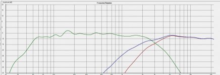
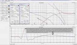
It’s taken a while but I’m finally testing the crossover with the intender speakers and I was hoping you might be willing to express an opinion on what I should do next, I have listed below the setup of the XO so far.
I’m not really sure what is going on with the phase??
I’m also not sure what’s going on with the saw tooth between 55 & 110Hz it is quite pronounced with RAW measurements especially when taken inside")
Any advice would be welcome.
- · Low Pass set at 150Khz
- · 6db Baffle step set for baffle width
- · 4th Order HP at 2100Hz
- · 4th Order LP at 2100Hz
- · All Pass on Tweeter set for 8.5mm
- · Woofer Output Linked= No Attenuation
- · Tweeter Attenuated for falling response to HF
- · Have a Notch at 700Hz
- · Have a Peak at 250Hz
- · I wouldn’t mind to put in a Low Cut to stop anything below 30hz getting to the woofers but am not sure how to go about it.
I’m not really sure what is going on with the phase??
I’m also not sure what’s going on with the saw tooth between 55 & 110Hz it is quite pronounced with RAW measurements especially when taken inside
Any advice would be welcome.
Attachments
A small wide notch around 7-800 Hz looks like it might be a good idea. I wouldn't try to boost that notch at 250 Hz.
What happens to phase and frequency response when you invert the tweeter? It looks like the tweeter is at a phase wrap and the woofer is almost at zero.
The low frequency ripple is probably floor/ground bounce. Probably nothing you can correct in the crossover, look to placement.
A "low cut" would be another high pass section, requiring another set of boards. Are you using this speaker with a subwoofer? If so the processor's subwoofer crossover will take care of that for you if you set the size to small.
What happens to phase and frequency response when you invert the tweeter? It looks like the tweeter is at a phase wrap and the woofer is almost at zero.
I'm a bit confused by the phase thing, as the tweeter has an All Pass section I was expecting to have to invert the tweeter but when I do, the FR has a large dip at the XO as shown below.
When you say phase wrap, what do you mean by "wrap"?
Attachments
Well the notch has worked as you will see, this is an inside measurement. Thanks
I was wondering why you thought I shouldn't bother with the second notch at lower frequencies?
Is it ok to have 2 filters (say 2 notches or a notch & Peak) on the one driver?
I was wondering why you thought I shouldn't bother with the second notch at lower frequencies?
Is it ok to have 2 filters (say 2 notches or a notch & Peak) on the one driver?
Attachments
Analogair, the buy fizzled as we didn't get enough interest to hit a reasonable price on the boards.
DQ828, I was referring to the 250 Hz notch in response in your outdoor measurements. Errors in omission are less audible than spikes in response if it is real. LF measurements are tough to do other than nearfield even outdoors. You are still likely to get ground bounce influence. Check out Linkwitz for a measurement method that might get more accurate results. You'll need a way to get your speaker up in the air.
The current 180 Hz bump relatively small and in the area that it is probably a room/measurement artifact. (since you said you measured indoors, you can confirm this by measuring in a different part of the room and/or at different distances.) You don't mention your baffle step frequency, but your response is relatively flat below the bump, just a couple dB lower. If the bump is not a room effect, could a bit more baffle step make the bump less obvious?
No, there is no "only one eq per driver" limit. Go ahead and try a 180 Hz notch if you like.
On the topic of measurements, have you done off axis measurements? Power response is a major factor in the sound of a speaker. I'd give up a bit of on axis flatness if it helps power response. Look for smoothly falling response off axis, without significant bobbles in the crossover region. Try 15°, 30°, 45° and 60° if you have the time. Do at least two off axis measurements.
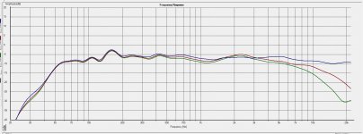
Hi Bob
Just when I thought I was finished
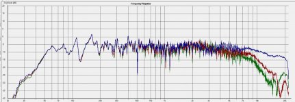
All of these measurements are taken Inside
The first image shows 0, 15 & 30 degrees
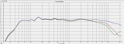
The second image shows 15, 30 & 45 degrees
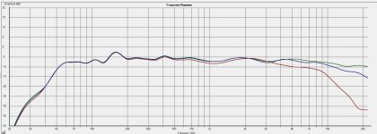
The third image shows 15, 30 & 45 degrees RAW
Not much is happening at the crossover, there is a large difference between 15 & 30 degrees.
I assume if I did want to use multiple filter on the one driver I would just daisy chain them?
At the EQ In & Out points there are ground connections which I'm not using, what are they for?
Just when I thought I was finished
All of these measurements are taken Inside
The first image shows 0, 15 & 30 degrees
The second image shows 15, 30 & 45 degrees
The third image shows 15, 30 & 45 degrees RAW
Not much is happening at the crossover, there is a large difference between 15 & 30 degrees.
I assume if I did want to use multiple filter on the one driver I would just daisy chain them?
At the EQ In & Out points there are ground connections which I'm not using, what are they for?
Attachments
Last edited:
Off axis transition looks pretty smooth through the crossover region. I'd bet you'd find similar off axis response on the tweeter alone. You might try a little felt near the tweeter, since there is a slight increase in off axis response compared to on axis just above XO. Probably a diffraction effect.
I'd be inclined to call it pretty close to finished and live with them a while. Then if you feel that 180 Hz bump needs work, give it a try. Female vocals would probably bear out any real problem in that region.
I'd be inclined to call it pretty close to finished and live with them a while. Then if you feel that 180 Hz bump needs work, give it a try. Female vocals would probably bear out any real problem in that region.
Off axis transition looks pretty smooth through the crossover region. I'd bet you'd find similar off axis response on the tweeter alone. You might try a little felt near the tweeter, since there is a slight increase in off axis response compared to on axis just above XO. Probably a diffraction effect.
I'd be inclined to call it pretty close to finished and live with them a while. Then if you feel that 180 Hz bump needs work, give it a try. Female vocals would probably bear out any real problem in that region.
I'm with you, I'm calling it quits for the moment, time to do some listening.
I have to put the second XO together and order a couple of caps but now I'm getting close to the end of a project that's been going a year. Was going to be finished last Easter
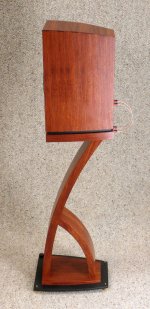
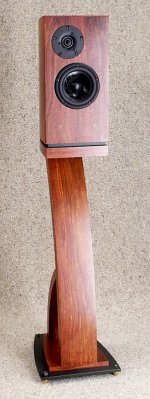
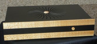
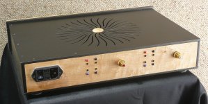
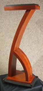
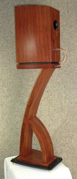
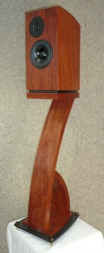
I've built a pair of these speakers/stands & the AmpXO, about 90-95% finished.
Thanks for all the help.
Attachments

Last edited:
You could play with it, again keeping an eye on off axis response. The higher you go the more the midwoofer will beam, possibly causing a sharp shift in dispersion at crossover. Your polar response looks good now, but may work a bit higher as well. Probably 7K will be way too high.
I'm with Andrew, 3.5K is about as high as I'd go based solely on your on axis FR. I tend to push tweeters as low as their distortion performance allows, shooting to keep the narrowing dispersion all in the tweeter. But that's me. Others shoot to keep the crossover higher.
Beautiful build, by the way.
Beautiful build, by the way.
Thanks.
So much for listening
off to 3000Hz we go.Thanks AT & Bob for the advice
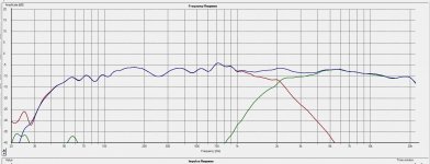
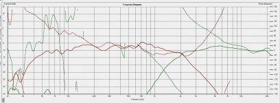
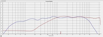
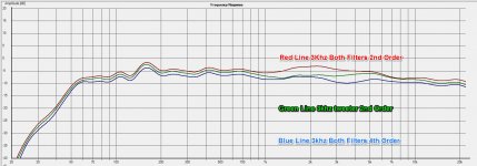
I have moved the XO to 3khz, I started with both drivers having 4th Order filters (3rd image Blue line) and the overall affect was the signal was generally a couple of db lower between 2&10khz with a more pronounced dip (compared to the 2.1Khz OX it's not phase related) at about 3-3.5Khz.
I then tried 2nd order filters for both drivers & had a a large dip! I then inverted the Mid and had a Peak back towards 2.5khz (3rd image Red line)
In the end I tried the tweeter as a second order and the mid as a 4th order and got the flattest line (3rd image Green line). I'm not sure about the downside of using mixed filters but from what I have read people are doing it. I think the rolloff should be sufficient to not be an issue.
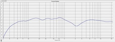
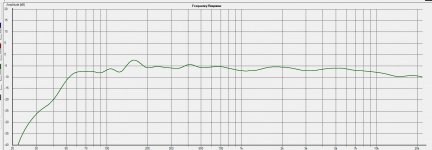
I tested the off axis at 15, 30 & 45 degrees and it looked pretty much as it did before. At this stage I have done a lot of testing but very little listening.
The first image shows the mid 4th order, tweeter 2nd & 4th Order
The second image shows off axis 0, 30 & 45 degrees with tweeter 2nd order & mid 4th order
I have lowered the Blue line on the 3rd image by 1dB and raised the red line by 1dB for clarity
I then tried 2nd order filters for both drivers & had a a large dip! I then inverted the Mid and had a Peak back towards 2.5khz (3rd image Red line)
In the end I tried the tweeter as a second order and the mid as a 4th order and got the flattest line (3rd image Green line). I'm not sure about the downside of using mixed filters but from what I have read people are doing it. I think the rolloff should be sufficient to not be an issue.
I tested the off axis at 15, 30 & 45 degrees and it looked pretty much as it did before. At this stage I have done a lot of testing but very little listening.
The first image shows the mid 4th order, tweeter 2nd & 4th Order
The second image shows off axis 0, 30 & 45 degrees with tweeter 2nd order & mid 4th order
I have lowered the Blue line on the 3rd image by 1dB and raised the red line by 1dB for clarity
Attachments
Last edited:
I wouldn't mind boosting the Mid output a bit and I was wondering if there would be any issues (sound wise) modifying the output op amp (IC9B) to a non-inverting gain stage like the attachment. I was only thinking of going to 1.1-1.3 something like that and probably using resistors around the 2k make for that purpose.
Attachments
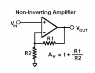
It would be much easier just pad the tweeter down more. If you need more attenuation you can reduce R21 to as little as 1K. A 10K pot and 1K gives up to 20.8 dB of attenuation.
You can make the output buffer a gain stage without issue sonically if you insist. Would be tough to do since it there isn't a long trace between the output and inverting input to make pads.
So how do the 3K XOs sound? All options shown look decent.
You can make the output buffer a gain stage without issue sonically if you insist. Would be tough to do since it there isn't a long trace between the output and inverting input to make pads.
So how do the 3K XOs sound? All options shown look decent.
Last edited:
It would be much easier just pad the tweeter down more. If you need more attenuation you can reduce R21 to as little as 1K. A 10K pot and 1K gives up to 20.8 dB of attenuation.
You can make the output buffer a gain stage without issue sonically if you insist. Would be tough to do since it there isn't a long trace between the output and inverting input to make pads.
So how do the 3K XOs sound? All options shown look decent.
Unfortunately I've disappeared up my behind trying to get a handle on the phase side of things so I haven't done any actual listening!! We have had thunderstorms almost every night for the last couple of weeks so that hasn't helped. There doesn't seem much point putting in a All Pass if you cant work out what affect it is having. I'm going to do so more testing tomorrow, if I don't make any phase progress I'll just do something sensible and play some music like I threatened to weeks ago.
The reason I asked about boosting the mid was because when I retested the tweeter without the crossover I was surprised how much louder it was. The Mid has a link in the pot output so it's at full volume. I just thought if I boosted the mid a bit I'd get more out of the tweeter & I was sick of thinking about th phase
I have been listening to the speakers in the last couple of days, the sound is possibly a bit high through the mid section than I would like but I am not sure there is much I can do about that.
My speakers are 3W Active driven OB's that really have a wonderful sound stage so the box bases 2W was always going to be challenged in that area and as I expected the SS is nowhere near as expansive or well defined. The SS also tends to move around a bit with frequency, if anyone knows what causes that I be interested to hear.
Having said that I'm sure my sister will be impressed (they do sound good) even if I don't make any improvement from here.
I'm glad to say the project is finished and delivered, my sister is very happy.
I'd like to thank you very much for all of the assistance that you have given me throughout this trying time
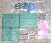
If anyone is interested I have 2 crossover boards, 1 PSU board and a pile of parts. I think all of the parts are there for the PSU and the Crossovers have the PSU input caps and the bypass capacitors for the OPA's but thats it for the crossover. PM me if your interested.
Many thanks again.
I'd like to thank you very much for all of the assistance that you have given me throughout this trying time
If anyone is interested I have 2 crossover boards, 1 PSU board and a pile of parts. I think all of the parts are there for the PSU and the Crossovers have the PSU input caps and the bypass capacitors for the OPA's but thats it for the crossover. PM me if your interested.
Many thanks again.
Attachments
Last edited:
- Status
- This old topic is closed. If you want to reopen this topic, contact a moderator using the "Report Post" button.
- Home
- Group Buys
- Active filter board GB