Hi Bruno,
I received the boards, very nice, thank you.
In post #65 attached circult, VR101 is 50K, however, I found in another link, the VR is 200 ohm. it could be to typo error.
http://www.kk-pcb.com/alephx.html
For the rectifier board, what is the value of R & C (example C1 & R1) ? Also, do you intend to use MUR30 (MUR3020WT) or MUR1560 for the Aleph-x ?
regards.
Recitifier Boards
Bruno,
I believe there is a problem with my recitifier boards. There is continuity between V- and both transformer lines AC1 and AC2. The problem appears to with the 1N4004 diodes in sections 3 and 4. On the top side both holes for this diode, in each of these sections, is connected to AC. On the back side in section 4 both holes are connected to V-. Can others verify? Thanks.
Re: Recitifier Boards
Hi all,
well, I verified it and... you're right, there is a mistake!!!

Ok, now there' s just two solutions: either I refund the money for the rectifier boards (including the relevant paypal fees) to all of you, or I will make a new run of corrected boards and send all of you the replacement (of course, I will pay for shipping).
Please let me know what you would prefer.
I apologise once again for this mess...
Cheers,
Bruno
t3447ml said:Bruno,
I believe there is a problem with my recitifier boards. There is continuity between V- and both transformer lines AC1 and AC2. The problem appears to with the 1N4004 diodes in sections 3 and 4. On the top side both holes for this diode, in each of these sections, is connected to AC. On the back side in section 4 both holes are connected to V-. Can others verify? Thanks.
Hi all,
well, I verified it and... you're right, there is a mistake!!!
Ok, now there' s just two solutions: either I refund the money for the rectifier boards (including the relevant paypal fees) to all of you, or I will make a new run of corrected boards and send all of you the replacement (of course, I will pay for shipping).
Please let me know what you would prefer.
I apologise once again for this mess...
Cheers,
Bruno
Recitifer Boards
Bruno,
I did not think this is a big problem requiring new boards. I was going to cut out the offending paths. Do you or any one else see a problem with this? Sorry I did not include this comment in my original post. Thanks again and I'm still in your debt.
Bruno,
I did not think this is a big problem requiring new boards. I was going to cut out the offending paths. Do you or any one else see a problem with this? Sorry I did not include this comment in my original post. Thanks again and I'm still in your debt.
Well,
cutting the offending paths would solve the problem, yes...
BTW, the silk screen for the 1N40XX diodes in sections 3 and 4 is also wrong, they should be mounted the other way round
The point is, I am responsible for this mess; I would feel better with myself making a new run of corrected boards and shipping them to all of you.
Of course, it will take some time (about 3 weeks again) but, if it's OK with you, I will order the new boards on Monday.
Cheers,
Bruno
P.S.: As for my post #68, I cancelled the order of those who just disappeared and updated the WIKI accordingly
Carondimonio said:Well,
cutting the offending paths would solve the problem, yes...
BTW, the silk screen for the 1N40XX diodes in sections 3 and 4 is also wrong, they should be mounted the other way round
The point is, I am responsible for this mess; I would feel better with myself making a new run of corrected boards and shipping them to all of you.
Of course, it will take some time (about 3 weeks again) but, if it's OK with you, I will order the new boards on Monday.
Cheers,
Bruno
P.S.: As for my post #68, I cancelled the order of those who just disappeared and updated the WIKI accordingly
Have my PCB shiped?
Hi everybody !
Looking at my PCB, I can see the mistake. No problem with me.
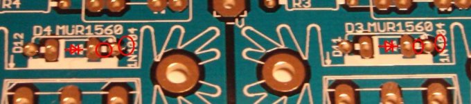
To illustrate how little the problem is, this first picture show the 4 paths to cut on the top face, there are 2 other paths (same size) on the back face (only Zone 4)
I just made the correction a few minutes ago and tested with my multi and it sounds to be good.
Correct me if I'm wrong !!!
(I don't have any other pictures to show tonight, my girlfriend is sleeping in the bedroom where my camera is))
I'll will post new pictures tomorrow if nobody else does it before.
Good night
Looking at my PCB, I can see the mistake. No problem with me.
To illustrate how little the problem is, this first picture show the 4 paths to cut on the top face, there are 2 other paths (same size) on the back face (only Zone 4)
I just made the correction a few minutes ago and tested with my multi and it sounds to be good.
Correct me if I'm wrong !!!
(I don't have any other pictures to show tonight, my girlfriend is sleeping in the bedroom where my camera is))
I'll will post new pictures tomorrow if nobody else does it before.
Good night
Attachments
Bruno,
i also noticed the problem with the rectifier boards.
Just cutting the traces is fine by me too, no need to have new boards made. The identified errors on the rectifier boards so far are tiny and can be corrected as good as invisible.(unlike some other GB boards)
May i suggest a second time to check ALL boards AND layouts thoroughly before each of us starts assembling.
How about posting detail pictures of every problem area, and a description of a clean way on how to cut the traces, on this thread ? I'll place the boards on a milling machine and machine the traces off without visible marks, perhaps someone can suggest a method for those without first aid skills.
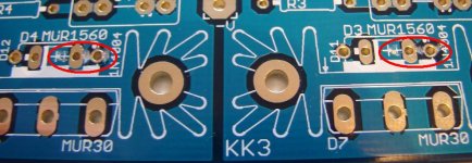
and on the back :
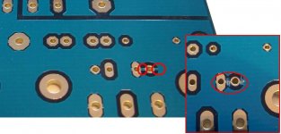
you can do a very clean correction, much better than my first attempt (this pictures).
I just cut a very little path on my other PCB and it works.
I was too tired last night, and I had not enough light.
thank's again to Bruno
Antoine
you can do a very clean correction, much better than my first attempt (this pictures).
I just cut a very little path on my other PCB and it works.
I was too tired last night, and I had not enough light.
thank's again to Bruno
Antoine
Attachments
Hi all,
well guys, you' re all really nice, thanks a lot for the nice words.")
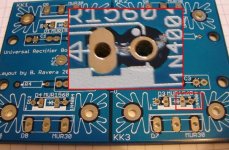
I've decided anyway to make a new run of corrected boards, this matter really bothers me and I want to solve it the best possible way.
Here's the corrected layout; I believe I fixed all the problems, but I would like to hear your opinion...
Cheers,
Bruno
well guys, you' re all really nice, thanks a lot for the nice words.
I've decided anyway to make a new run of corrected boards, this matter really bothers me and I want to solve it the best possible way.
Here's the corrected layout; I believe I fixed all the problems, but I would like to hear your opinion...
Cheers,
Bruno
Attachments

Hi all,
well guys, you' re all really nice, thanks a lot for the nice words.
I've decided anyway to make a new run of corrected boards, this matter really bothers me and I want to solve it the best possible way.
Here's the corrected layout; I believe I fixed all the problems, but I would like to hear your opinion...
Cheers,
Bruno
Attachments
- Status
- This old topic is closed. If you want to reopen this topic, contact a moderator using the "Report Post" button.
- Home
- Group Buys
- Aleph-X Compact PCB Group Buy