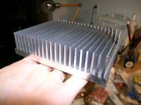
I am going to create a drill template for the heatsinks, and will include it with all the kits whether or not you got a heatsink. Also, I would recommend mounting the 3886's to the heatsink, THEN soldering them to the board to be sure the edge-of-board alignment is correct.
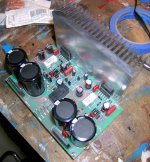
PS: that's my wife's messy workbench (painter). Mine is covered with Aleph, Leach, and Nikko parts.
PS: that's my wife's messy workbench (painter). Mine is covered with Aleph, Leach, and Nikko parts.
Attachments
 Amps parts are consider decoration, not clutter.
 Hi Russ & Brian,
2 suggestions:
- I have seen (by the photo) that the diodes bridges are "thin". I imagine that are predisposed ( with a hole ) to be fixed in a headsink. When you do the first test, verifies that the temperature of this bridges doesn't increase too ( 40WRMS 8 ohm ). If it overcomes the 60-70 °C be necessary fix a foil of aluminium for headsink.
- Same does by R1, R4, R24, R27. If it heats over the 70 °C it be necessary find a model with more "headsink" surface (like 2W wire model).
Sorry, I don't want create "problems" but it is better some incident of supply that of the problems of operation...
ciao
Mauro
When I mounted those resistors, I lef tthem raised above the board by a few mm to allow heat disapation. I am always amazed how small resistors are getting. I will be powering it tonight (hopefully) from a 22V (44vct) transformer to check it out. I will keep a close eye on the temps.
If it turns out the bridges need a bit of heatsinking, I can include some flat pieces of aluminum in the kit to be used. They are rated for 8A each, and I am hopeful they will be fine.
Thanks again for everything Mauro.
I was thinking of incuding a small and brief construction guide, mostly an order in which to mount the parts and some tips such as spacing the 1W resistors, etc.
BrianDonegan said:Possibly. The resistors are stable until 70C where they begin to derate. If they reach that point, we should probably switch them to 2W as Mauro suggests. Those will be the concentration of my tests.
Sounds like a plan!
")

Member
Joined 2003
Don't forget to put the op-amps in the socket as well . I've done that before.
Do the LM3886 chips need to be electrically separated from the heatsink, or can I just slap some paste in between them? If I do need to separate them, what should I use? We used kapton film at school, but my local electronics supply store will only sell it in large expensive rolls. What would you recommend for best heat transfer?
. I've done that before.Do the LM3886 chips need to be electrically separated from the heatsink, or can I just slap some paste in between them? If I do need to separate them, what should I use? We used kapton film at school, but my local electronics supply store will only sell it in large expensive rolls. What would you recommend for best heat transfer?
Member
Joined 2003
Making music!!
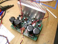
Powered up fine on the first shot. Sounds great. Need to let it burn in for a few, and I am only listening through my Cambridge Soundworks workbench speakers, but all it well.
The bridges are still cold after about 20 mins. The heatsink is just detectably warm. The 1W resistors are warm. They are dissapating approx .46W with my 22V transformer, so I think they are okay for now.
Attachments
Woow,
is a lot of strange to see the "birth" of my work to "distance".
From planner comes me birthmark to ask you: You have verified the voltages, the currents, the temperatures, the relay timing... but then realize me that surely my "creature" is in good hands...
To the limit you verifies with an oscilloscope that not are "bewilder" oscillations, but I believe that you it has already done...
For the "sound", there are not problems. Already with the basic kit it doesn't fear comparisons with the greatest part of the "classical" solid-state ( Borbely, D.Self, GC... ) and if you is wants the maximum enough make a will it my "variations" (actual & future)...
Ciao
Mauro
BrianDonegan said:I was thinking of incuding a small and brief construction guide, mostly an order in which to mount the parts and some tips such as spacing the 1W resistors, etc.
That would be excellent!
Good looking build!
Originally posted by BrianDonegan: I was thinking of incuding a small and brief construction guide, mostly an order in which to mount the parts and some tips such as spacing the 1W resistors, etc.
Please include your findings/experience with fasteners: sizes. tapped or self-tapping, etc. Looking at the position of the big caps I can see they could make drilling the heatsink a pain. Knowing the order in which to proceed would save a lot of grief.
Congrats!
I don't own an oscilliscope, so I couldn't check for ocillations. I wired up the last few parts before getting ready for work, so I only had a few minutes to play. I would assume that if it was oscillating, the heatsinks would be getting hotter than they did (just warm). Not proof, but good enough to get me through the day.
I did not measure voltages, other than across the 1W resistors (~22.5V i think). The turn-on delay was about a .25-.5 seconds. I first powered it with a 75Watt light bulb in line with the mains. The relay kicked on after the bulb flashed. The relay also cuts out imeadiately on power-off, so there is no turn-on or turn-off noise/thumps/pops.
I will do more investigation this evening. My wife is actually going to be assembling the kits with me. I'll let you know how that goes.
I have made several construction notes that I will include. Here are a few in no particular order (will be included in the kits):
- Put the jumpers on before the big caps. I put them on last and had to use needle nose pliers to insert them.
- Big caps shoudl be the last thing you mount.
- I used my drill guide to mark the holes. I used a 7/64th drill bit and tapped 6-32 threads, about 5/16" deep. I used 5/16" 6-32 buttonhead screws with washers.
- The 3886s mount ever-so-slightly in from the edge of the board. I mounted my heatink so the bottom is flush with the bottom of the board, and needed to convince the pins they wanted to go into the holes in the board. Perhaps mounting flush with the top of the board would be better.
- I mounted the 3886s to the hetsink first, slightly loose. Then inserted the pins into the holes on the board, soldered, and tightened the screws. Since my screws were hex driven, I was able to tighten them up with the big caps in place. If done again, I would mount the big caps last.
- Place some standoffs on the component-side of the board, allowing you to place the board upside down on the workbench when soldering.
- The Faston connectors are a very tight fit in their mounting holes. I used a small drill bit, twisted with my fingers, to open up the holes very slightly from the component side, but not all the way through. I then used some fine tip pliers and a gentle circular motion to seat them.
- When soldering the 3886s, do one row of pins on each chip, then the second row. This give the chip a little time to cool down from the first row of soldering.
All I can think of off the top of my head (at work now).
- Status
- This old topic is closed. If you want to reopen this topic, contact a moderator using the "Report Post" button.
- Home
- Group Buys
- Mauro Penasa's INV GC/REF GC group buy.