Stevox/ Peter- thanks for the confirmation. How about a pic?
Mr. V, yes we have been through a lot, but you KNOW that I'm not that smart and that most of our time involved you guys answering my bad questions, so don't be surprised when I get lost...hope you are enjoying your time abord those luxury boats, the GPS working good? Of course. Stay on course. Hmmm...... when can we see a finished project from you 2007? 2008? How are those pink Ikea resistor lead spacers working out?
Mr. V, yes we have been through a lot, but you KNOW that I'm not that smart and that most of our time involved you guys answering my bad questions, so don't be surprised when I get lost...hope you are enjoying your time abord those luxury boats, the GPS working good? Of course. Stay on course. Hmmm...... when can we see a finished project from you 2007? 2008? How are those pink Ikea resistor lead spacers working out?
Mr Green,
you know very well i spend way too much time shopping for fun parts.
I've got something to post shortly, let's be very silly and make it 2007.
(i have a homebuilt laptop GPS on the boat, but it hasn't been working that great over the last decade)
you know very well i spend way too much time shopping for fun parts.
I've got something to post shortly, let's be very silly and make it 2007.
(i have a homebuilt laptop GPS on the boat, but it hasn't been working that great over the last decade)
Attachments
promitheus said:Hi I am back!
Sorry to not have answered to your emails.
I was away for a week.
60% of the Orders are sent.
I will post tomorrow which ones are already sent the rest will be sent till the weekend.
Still no list, no package, no information and no response on my e-mail.
Still waiting


smario said:
Still no list, no package, no information and no response on my e-mail.
Still waiting
Me too- sorry to pester, waiting patiently. ('
") ')
')I'm still waiting too, but am thinking about how to best implement the Pearl boards. My plan is to build the Pearl and an Aleph P 1.7 (using Veteran's PCBs), and will probably put the power supplies for both in a single separate chassis. Does it make sense for me to try to cram the Aleph P, the Pearl and a remote control systems from Dantimax into one enclosure, or should I put the Pearl PCBs into their own box? That would mean at least 3 enclosures (Aleph + Pearl PS, Aleph P + Dantimax RC system, and Pearl).
Is there a smarter way to do this?
Thanks for the recommendations!
Regards,
Scott
Is there a smarter way to do this?
Thanks for the recommendations!
Regards,
Scott
Hello,
sorry that I cant answer your emails personaly.
I had to go away again on a trip for work:

I thought I would have more free time but since I started with the group buy its no going so well as I thought.
I am very sorry to delay the last KITs but they will be there soon.
sorry that I cant answer your emails personaly.
I had to go away again on a trip for work:
I thought I would have more free time but since I started with the group buy its no going so well as I thought.
I am very sorry to delay the last KITs but they will be there soon.
promitheus said:Hello,
sorry that I cant answer your emails personaly.
I had to go away again on a trip for work:
I thought I would have more free time but since I started with the group buy its no going so well as I thought.
I am very sorry to delay the last KITs but they will be there soon.
Is there a full 2-channel kit left?
It sounds as though you have had a lot of work on this already!
TIA
Cliff (UK - paypal)
cliffforrest said:
Is there a full 2-channel kit left?
It sounds as though you have had a lot of work on this already!
TIA
Cliff (UK - paypal)
How do I edit my post ??!!
I am referring to a dual MM configuration + PSU
Ideally PCB plus all parts, but PCB plus Semis will be OK.
cliff.forrest@gmail.com
1. Why are the input AC resistors on the AC part of the power supply 1/2 watt 4.7 ohms when the next ones downstream are 3 watt 4.7 ohms? Are the 1/2 watters going to be ok?
2. Why does the board say for C11, "connect here for soldered grounds" or something like that that?
2. Why does the board say for C11, "connect here for soldered grounds" or something like that that?
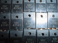
jacco vermeulen said:Monsieur Vert,
for Q1, take a look at THIS
Hint: body lengths of Panasonic metalfilm R's are 9mm-1W, 12mm-2W, and 15mm for 3 Watt types.
Eeeh, Q2 : the wire link is the ground for C15, see right middle center of the PP schematic.
btw, seen my new socks ?
Q1- well are you trying to say one can deduce from the pic that they are small so Pass used 1/2 watters everywhere?
The article says "The circuit draws about 50 mA per channel, so you are looking for a voltage drop across R2 of about 0.25 volts." So .05^2R = .0025*4.7 = .01175 watts. So even a 1/4 watt resistor should be fine.... in theory.
Q2- That's what I thought but I seem to recall that when I probed the board C15 was already connected to ground on that pin making a wire there unnecessary?
socks? is your icon different or did I miss a post somewhere?
Señor Verde,
you can deduce from the pictures, the BOM, and the separate article pages on the Pass labs site that the Pearl Phono package is not entirely consistent.
The DK number for a Panasonic 3 watter is mentioned, P4.7W-3BK-ND.
But the text refers to a 2 watt resistor, which would be a P4.7W-2BK-ND.
Bare in mind that Mr Colburn can grab parts from the pile stacked storageroom at Pass labs, and Herr P is a lean and mean logistic machine.
Forget transformer losses: Vin * Iin = Vout * Iout
Vin=120Vac, Vout=30Vac=> ~Iout = 4 * Iin.
Take Iin = 1/4 * 50mA= 12.5mA
Let's take the peak value= sqrt(2) * 12.5mA= 18mA.
Suppose the peak inrush current is 10 times higher, considering that most PP builders will be using a donut => 10 times makes 0.180 amps. The inrush peak only lasts a couple of milli-seconds, peak inrush dissipation of the 4.7 ohm resistor is very small.
sqr(0.18) * 4.7 Ohms = ~0.15 Watt
The resistors on the primary side of the transformer survive continuous operation at 180mA if they were 0.25W types.
Mr Colburn started as P's protegé, he'll follow NP's guideline of using twice the wattage rating=> 1/2 watt.
You Krenegade you : SOCK it
(ps: check my caps 3 posts down the line , i found 8.5K of them beauties)
Hello,
Scott you are not the last one.
I sent all the KITs today so they should be there in the next week.
daylne52 and lgreen haven´t paid yet so please contact me.
I sent your packages and after I saw that your payments through paypal weren´t completed. Please accept the paypal invoice or if you cant find it please contact me to close the transaction.
For those who are interested in KITs or parts I have a few so contact me.
jacco vermeulen said:Señor Verde,
you can deduce from the pictures
***
The resistors on the primary side of the transformer survive continuous operation at 180mA if they were 0.25W types.
***
You Krenegade you : SOCK it
(ps: check my caps 3 posts down the line , i found 8.5K of them beauties)
That's weird, I remember reading your cap post but not the resistor one w/ the nylon. When you sail to the west coast I will give you a cargo manifest (right word?) of all the parts you need to bring me.
I have used two 1/2 watt 10 ohm resistors in parallel as I could not find a 4.7 ohm one, so this should be safe.
Except that my power supply unloaded (no boards, 1st stage only) gives me 47VDC so I am getting nervous that the 50VDC caps may be close to tolerances. I am using two of These 15-0-15 25 VA transformers. Have not loaded this down yet with the channel boards but don't think it will drop that much. I may cut out one of the resisitors to get a higher voltage drop if things don't change once the boards are hooked up.
promitheus said:Hello,
**
daylne52 and lgreen haven´t paid yet so please contact me.
Promitheus, you are back! I mentioned in Post #430 that I received the package but no paypal invoice and did not recall paying. Looks like I was right. Just paypal me at--- lgreen **at** parttimeprojects **dot** com (or email me by clicking the link/ etc...). I've emailed you the same info.
Kind of funny (not for you) but I am almost done (full Pearl scheduled for completion tomorrow) and i've not paid yet...I feel so guilty.
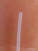
lgreen said:the nylon.
Took me some effort to find teflon tube this thin, it's only 0.08" diameter.
Funny thing, it's less than a dime the feet.
If you want some, let me know.
Bill-Of-Lading HERE ,but i only accept one that is completely filled out.

(wonna see the supercool heatsinks i have for the ExtremeA's ?)
Attachments
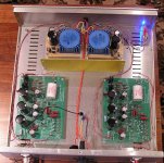
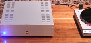
Here is My "pearl" - thanks for the boards
yes yes yes!!
FYI, finally got the paypal invoice and paid....Hopefully that really was Promitheus who sent me the invoice...
Good thing too, the Pearl is up and running. It has a little more hum than I'd like but I am experimenting with grounding and have already dropped the hum a lot just by connecting output ground to case ground (weird since this really fixed one bad channel..other was pretty quiet). And that 3rd wire from the turntable is confusing me, figuring out how to ground that one. As you can see there are not many wires going to the star ground.
The shielding plate is cold rolled steel. DC voltages measure close to what the Pearl article says you should get. Inputs and Outputs are isolated but all grounds wired together.
jacco vermeulen said:
***
(wonna see the supercool heatsinks i have for the ExtremeA's ?)
yes yes yes!!
FYI, finally got the paypal invoice and paid....Hopefully that really was Promitheus who sent me the invoice...
Good thing too, the Pearl is up and running. It has a little more hum than I'd like but I am experimenting with grounding and have already dropped the hum a lot just by connecting output ground to case ground (weird since this really fixed one bad channel..other was pretty quiet). And that 3rd wire from the turntable is confusing me, figuring out how to ground that one. As you can see there are not many wires going to the star ground.
The shielding plate is cold rolled steel. DC voltages measure close to what the Pearl article says you should get. Inputs and Outputs are isolated but all grounds wired together.
Attachments
- Status
- This old topic is closed. If you want to reopen this topic, contact a moderator using the "Report Post" button.
- Home
- Group Buys
- Pearl phono PCBs Group Buy