STOP!!!
It looks great! Yes, it could be tweaked to death - but let's let Brian get on with it...!!! That way we can all build something (in THIS millenium) ... and we can always ***** about it later if it doesn't work out..")
When can we place orders? BTW, thanks Brian for going through all the trouble - I know alot of people here appreciate it.
And it will NEVER be "perfect". If you want perfect, you can believe the marketing crap from any number of commercial suppliers and - guess what(?!!) - they lied, it isn't perfect.
FASTER!!!!.......
Regards,
Bill
It looks great! Yes, it could be tweaked to death - but let's let Brian get on with it...!!! That way we can all build something (in THIS millenium) ... and we can always ***** about it later if it doesn't work out..
When can we place orders? BTW, thanks Brian for going through all the trouble - I know alot of people here appreciate it.
And it will NEVER be "perfect". If you want perfect, you can believe the marketing crap from any number of commercial suppliers and - guess what(?!!) - they lied, it isn't perfect.
FASTER!!!!.......
Regards,
Bill
Re: STOP!!!
I prefer to wait longer and something better than the other way around. But that is just me and who is that me is
netgeek said:It looks great! Yes, it could be tweaked to death - but let's let Brian get on with it...!!! That way we can all build something (in THIS millenium) ... and we can always ***** about it later if it doesn't work out..
I prefer to wait longer and something better than the other way around. But that is just me and who is that me is
Re: Re: STOP!!!
Waiting - up to a point - is a good thing... But we've reached a point, I think, where minor quibles are slowing progress.
BTW, my comment about "*****ing" got screened? (Reference to a female dog - starting with "B"). Wow, the filters here are really good - and the moderators must have the "sensibility threshold" set to "MAX"...???
roibm said:
I prefer to wait longer and something better than the other way around. But that is just me and who is that me is
Waiting - up to a point - is a good thing... But we've reached a point, I think, where minor quibles are slowing progress.
BTW, my comment about "*****ing" got screened? (Reference to a female dog - starting with "B"). Wow, the filters here are really good - and the moderators must have the "sensibility threshold" set to "MAX"...???
Variac said:It occured to me that it might be good to have the 2 rows
of diodes in the power supply facing in opposite directions or
some other idea so that they could be all be attached to
heatsinks. MAybe this would only be important if the bridge were used for 6 100w channels- but many people are probably going to make bigger ampps with this kit. Also would be very useful if someone wanted to use just the power board for a Son of Zen or other big class A amp. Then they would be like Big Parsnips diode boards? (but without snubbers) So only an idea if it doesn't compromise something. What is the capacity in amps for the assembled bridge? Would small heatsinks double the rating?
Second- thank you for my latest order. Excellent counting!!!
BUT (I hope this doesn't drive you over the edge) It's missing the 2 small BlackGate caps for the power supply. They are supposed to be part of the premium bridge kit , right?
Mark,
Small heatsinks might double the rating. I will think about it, as I am working on the new diode board design now. I will see what Peter thinks about it.
I will mail you out 2 more BG 4.7uF N caps. Sorry for the mistake.
--
Brian
I was reading that too and it seems like a good idea. I noticed that sometimes the diodes warm up quite a lot so having some sort of heatsink bar would help with disippation. This would require fliping diodes in the other row to have the taps on the inside. It shouldn't complcate the traces too much. But I think that one flat bar piece, 1/8 thick and sized approx 1 x 3 should be enough. Don't go with separate heatsinks as this will add unnecessary bulkiness. Of course adding isolation pads would be required.
The board looks really nice now, isn't it?
The board looks really nice now, isn't it?
I have a technical question to those who know more about board design. It seems like adding a track from pin 17 south to connect it with V+ plane would increase current supply to that pin. Yet it creates a loop. Is it good or bad?
Also, would trimming both power planes on the sides, like on LM3875 boards, would be recommended? This would somehow decrease the unused area of the plane and help in directing current where we really want it, towards the caps.
This is more or less theoretical, but this thread is pretty much educational regarding board layout design and we didn't touch that issue yet
Re: STOP!!!
heh.. I wouldn't want to rush it. A couple extra days won't hurt anyone. After all, I would guess that over 1/2 of the people ordering the LM3875 kits haven't even started their projects yet.
Be patient, and you will be satisified with the end result.
--
Brian
netgeek said:It looks great! Yes, it could be tweaked to death - but let's let Brian get on with it...!!! That way we can all build something (in THIS millenium) ... and we can always ***** about it later if it doesn't work out..
When can we place orders? BTW, thanks Brian for going through all the trouble - I know alot of people here appreciate it.
And it will NEVER be "perfect". If you want perfect, you can believe the marketing crap from any number of commercial suppliers and - guess what(?!!) - they lied, it isn't perfect.
FASTER!!!!.......
heh.. I wouldn't want to rush it. A couple extra days won't hurt anyone. After all, I would guess that over 1/2 of the people ordering the LM3875 kits haven't even started their projects yet.
Be patient, and you will be satisified with the end result.
--
Brian
Re: Re: STOP!!!
Well, I ordered the LM3875 kit just this morning - and I hope to have it working within hours of receipt - then what..
I'll need the LM4780 boards very soon after that just to maintain a "fix"...
BrianGT said:
heh.. I wouldn't want to rush it. A couple extra days won't hurt anyone. After all, I would guess that over 1/2 of the people ordering the LM3875 kits haven't even started their projects yet.
Be patient, and you will be satisified with the end result.
--
Brian
Well, I ordered the LM3875 kit just this morning - and I hope to have it working within hours of receipt - then what..
I'll need the LM4780 boards very soon after that just to maintain a "fix"...
Re: Re: Re: STOP!!!
Well, I will get your LM3875 kits shipped out to you tomorrow, so you can started. I will try my best to feed your addiction, as it makes me feel better about having my own.
--
Brian
netgeek said:
Well, I ordered the LM3875 kit just this morning - and I hope to have it working within hours of receipt - then what..
I'll need the LM4780 boards very soon after that just to maintain a "fix"...
Well, I will get your LM3875 kits shipped out to you tomorrow, so you can started.
I will try my best to feed your addiction, as it makes me feel better about having my own.--
Brian
Capacitors 101
fwiw, Panasonic is offering a new electrolytic capacitor, the "FM".
It has lower impedance than the "FC" but passes a higher ripple current. Low impedance is recommended for the capacitors used as the FC is in the "standard" kit version.
What about higher ripple current? Is that a negative characteristic of the FM cap that outweighs its lower impedance?
I guess a listening test may be in order.
Also, it would be necessary to drop to a 35V rating to get anything above 1000 uF.
Thoughts anyone?
. This would require fliping diodes in the other row to have the taps on the insideBut I think that one flat bar piece, 1/8 thick and sized approx 1 x 3 should be enough
I think flipping a row so that they face both sides of a 1/8 or 3/16" bar is a great idea. Its a simple way to impliment what I was suggesting Also-really easy to through bolt , so only 4 hole need be drilled in the bar other than mounting holes for the bar itself. ( I was envisioning the rows facing out w/ a total of 2 heatsinks- too complicated!!)
It doesn't seem like it would take much if any more room on a circuit board, though Peter cleverly points out that insulators are needed- which also have thickness. If you sized it for an 1/8" bar
with alu oxide insulators, people could also use a 3/16" bar and mica insulators if they preferred. Of course they could also make the plate as large as they desired!
NP seems to say that sinks tremendously increase the diode capacity
thanks for considering this.
Mark
Variac said:I think flipping a row so that they face both sides of a 1/8 or 3/16" bar is a great idea. Its a simple way to impliment what I was suggesting Also-really easy to through bolt , so only 4 hole need be drilled in the bar other than mounting holes for the bar itself. ( I was envisioning the rows facing out w/ a total of 2 heatsinks- too complicated!!)
NP seems to say that sinks tremendously increase the diode capacity
thanks for considering this.
Mark
Sounds great to me as well. I will work with Peter to modify the layout to accomidate this.
--
Brian
maybe it was missed, but i would like to know if there will still be the mirror power connections for 2 boards as in one of Peter Daniels early sketches in the thread.
(doh now i cant find it, was the tread culled?)
anyhow it had the 2 boards facing opposite ways with the bridge board between them, the power was straight wires between each board because + and - were mirror imaged on the boards.
this would be a great feature, only if it doesnt compromise the design though.
This was the initial intention, yet in a process of designing a layout it came up that this would really compromise it , and as I look at it now, I don't think it was even possibe (without bending things too much). Majority will be still using this board in a parallel version only, so doing extra traces/planes just for mirrior matching connectivity didn't seem like priority.
However, what I consider now, is implementing the power connection to to boards (facing each other) with an additional, bridging board. This board and circuit is required to convert single ended signal into balanced one (for bridged operation), and basically, it's only DRV134 chip and PS regulators. The PS would be delivered from rectifying board and same power would be used for the amps and the bridging circuit (if I can call it like that). That board would also contain traces which would route power to both amp's boards, so mirror imaging (of amp's boards) is not required really.
I hope, I made myself clear on that idea.
Another vote for sinkable diodes. I suspect that with these higher power designs, they will be needed much more than the average gainclone, which is probably pushing 1W RMS. Some of these bridge/parallel designs may be tasked to EQ'd subwoofer duty, which has high RMS power.
Also, I personally would like to use some of these bridge PCBs to replace the integrated bridges in my A-X, and substantial heatsinking is required there.
Also, I personally would like to use some of these bridge PCBs to replace the integrated bridges in my A-X, and substantial heatsinking is required there.
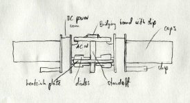
Here's another approach to simplifying connections in bridged version. You have 2 boards facing opposite ways with the bridge board between them.
To each of the amp's board, a rectifying board is attached. Short wires carry DC power as pads on both boards are aligned.
Both rectifying boards are tied together by heatsing plate, to which diodes are attached. There are 2 standoffs to mount that plate to main heatsink.
Additional standoofs provide mounting support for a bridging board, containing DRV134 chip and regulators and small bypass caps. The power to bridging circuit is taken directly from rectifying boards. There are only 4 wires to supply AC to both rectifying boards.
The rectifying boards have a ground plane on one layer, providing a shileding from diodes, also the bridging board has a ground plane and additional shielding is provided.
It seems like an interesting approach to bridging concept and this doesn't require mirrored boards.
Attachments
Oh .......... why not ?
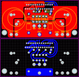
1. Where are the output networks (RSN1,2 CSN1,2)? The guys from National didn't put them on the schematic for fun. They need to be on the PC Board there seems to be room above the filter caps. They are part of the compensation for the amp and need to be there. I don't know why people want to leave these off or mount them on the binding post. PUT THEM ON THE BOARD.
2. The CHG terminal is for the ground return for the center tap of the transformer I take it. Put a pad right next to the OG pad, as close as you can get it. Separate diode bridges for each cap would be even better with returns directly to the filter cap GND terminals. Location of this ground return is critical for how much ripple noise shows up on the output.
3. Look at changing the V+ and V- connections to the chip to lower the resistance between the supply caps and some of the supply pins on the amp that have more resistance in their traces. Something like this picture maybe......
4. The rest of the layout is very good and I can't think of anything I would change.
Attachments
I suggest reconsidering the idea of orienting the diodes with the tabs facing outward (rather than towards each other), and using two heat sinks. This eliminates the possibility of large stresses on the diodes if the combined thickness of the heat sink and insulators does not exactly match the gap between the two rows of diodes. Also, two heat sinks provide twice the surface area for convection cooling, and allows the option of using finned heat sinks for even better convection cooling. Or, eight small finned heatsinks could be used, eliminating the need for insulators.
However, it would not work as well with Peter's bridged arrangement; cooling by conduction to the chassis/main sink is easier with the single, central PS heat sink.
My $.02
Phil
However, it would not work as well with Peter's bridged arrangement; cooling by conduction to the chassis/main sink is easier with the single, central PS heat sink.
My $.02
Phil
I guess Zobel discussion went already to far, so I created a separate thread for it: http://www.diyaudio.com/forums/showthread.php?s=&threadid=34130
Everybody interested in LM4780 board, please be assured that the board will feature a Zobel network.
Everybody interested in LM4780 board, please be assured that the board will feature a Zobel network.
- Status
- This old topic is closed. If you want to reopen this topic, contact a moderator using the "Report Post" button.
- Home
- Group Buys
- Group order of non-inverted LM4780 pc boards? Anyone interested?