Got the PSU stuffed for the most part except for the LEDs and diodes. The diodes will be mounted under onto the base plate and the LEDs will have a lead to the front panel.
Good looking board Shaan.
Thanks.
Man these cans are HUGE!!! 4 pin?
I also like the blue.
")
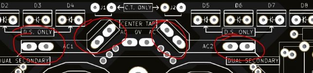
Edt: I see that you have installed a terminal in the center tap pad. Please remember that once assembled for either DS or CT secondaries the PSU will not accept the other secondary type. Just in case...
I'm only using the board as a PSU and have it hooked up to my PeeCeeBee 4 amp modules. I dunno why but I have better bass response than with the previous Ebay Chinese PSU I was using. Another winner from shaan. Thanks!
Glad to know you are enjoying the combo. I guess they were made for each other and you got the best result.
Thanks and happy listening.
Last edited:
Thanks.
Man these cans are HUGE!!! 4 pin?
I also like the blue.
Edt: I see that you have installed a terminal in the center tap pad. Please remember that once assembled for either DS or CT secondaries the PSU will not accept the other secondary type. Just in case...
Yep, 4 pin.
For the DS connection, I'm correct in using what's marked in the attachment right? Is the center 0V not just another ground tap? It won't hurt anything having an unused tab there will it? All the diodes will be populated and J1 and J2 will be open.
Attachments
Hi Shaan,
What's the magic number of boards before production begins?
50.
Thank you very much Shaan for the wonderful design's.
Thanks for your interest.
hello Shann
I have a small problem, the relays do not trigger after power on
the relay operates at 12volt and 275 ohm (R 9,10,11,12 is 275 ohm)
the power supply is 35volt.
an idea to find the fault?
Thank you
I have a small problem, the relays do not trigger after power on
the relay operates at 12volt and 275 ohm (R 9,10,11,12 is 275 ohm)
the power supply is 35volt.
an idea to find the fault?
An externally hosted image should be here but it was not working when we last tested it.
Thank you
hello Shann
I have a small problem, the relays do not trigger after power on
the relay operates at 12volt and 275 ohm (R 9,10,11,12 is 275 ohm)
the power supply is 35volt.
an idea to find the fault?
Thank you
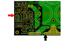
Hi Zebulo.
Please do the following.
Set multimeter to mV.
Connect the probes as marked in the attached picture.
Turn on power.
Please report what voltage you see.
Turn off power.
Please report what voltage you see.
Thanks,
shaan
Attachments
Last edited:
- Home
- Group Buys
- PeeCeeBee PSU GB