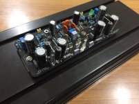
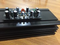
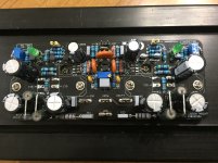
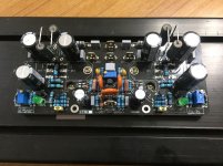
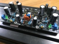
Shaan, do you have any remaining boards or an idea of when the next group buy will take place? I previously got the original V4 peeceebee, but have not built them yet. After the modifications and the release of this one, I'm wondering if I should just do this.
All the boards from last GB are taken. Next GB starts as soon as anyone posts username followed by number of PCBs.
Hi Shaan, one of the technical query for this board about the individual DC supply for the front end. If i use 35VDC for backend but use 38 ~ 40VDC for front end. Then how can i connect the front end rail to the board. And what component should be modified ? Thanks for your support in advance.
Hi Shaan, one of the technical query for this board about the individual DC supply for the front end. If i use 35VDC for backend but use 38 ~ 40VDC for front end. Then how can i connect the front end rail to the board. And what component should be modified ? Thanks for your support in advance.
Urrrgh sorry for late reply!
Remove D1+D2.
Connect +ve front end rail to the pad for D1's cathode pin.
Connect -ve front end rail to the pad for D2's anode pin.
Make sure both PSUs have a well terminated common ground node. Both PGND and SGND must be connected to that node either with individual wires or by connecting SGND to PGND first and then PGND to ground.
- Home
- Group Buys
- PeeCeeBee V4H GB
