Hi X,
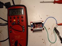
Here is a pick of how I left it yesterday. I dialed the voltage back to 26V. I used the same setup and changed the DMM to measure amps.
Are you saying to connect the resistor in series with - output and measure A across the resistor, while using a separate DMM connected across the outputs to monitor voltage ?

Hi,
Any other builders that have used the DC-DC-boost care to chime in with a procedure or diagram on how to connect components to test and set the current (if my hookup in #601 is incorrect). I can set the voltage, but the current does not vary throughout the range of the pot. Once I have a proper procedure, I will try a new boost converter, as I have a feeling I may have pooched this one. Thanks
Any other builders that have used the DC-DC-boost care to chime in with a procedure or diagram on how to connect components to test and set the current (if my hookup in #601 is incorrect). I can set the voltage, but the current does not vary throughout the range of the pot. Once I have a proper procedure, I will try a new boost converter, as I have a feeling I may have pooched this one. Thanks
Yes. To measure current, DMM must be in the circuit as a series element. Make sure it is in current (amps mode and not mA mode as that might blow the fuse). I have had a couple of these DCDC converters go bad. They are not the most high quality builds but at the price sold, we take our chances.Hi X,
Here is a pick of how I left it yesterday. I dialed the voltage back to 26V. I used the same setup and changed the DMM to measure amps.
Are you saying to connect the resistor in series with - output and measure A across the resistor, while using a separate DMM connected across the outputs to monitor voltage ?
View attachment 1239543
These 48v output converters are potted and have heatsinking. Maybe they are more reliable? I have not tried but probably will order one to test. Good for 3A.
https://a.aliexpress.com/_ms6F2Yk
Thanks X,
I understand that the DMM must be in series with the resistor. The question I have is: " Do I need to attach the positive side of the converter to the resistor like in my picture above, or can the current be set just by having the resistor attached to the negative side of the converter with the DMM across the resistor." This why I asked for a diagram of the hook up for setting the current, so I do not destroy another one. I purchased 4 converters a wile ago.
Also, thanks for the info/link to another variety of converter.
DMM "In Series with" the resistor. Not in parallel with the resistor => Not across the resistor.
Green lead to Black probe of DMM set to 10A (and probes in proper holes) - red probe of DMM to resistor - other side of resistor to blue lead. That is in series.
Just ensuring clarity. You may have done this in a different post / picture.
Green lead to Black probe of DMM set to 10A (and probes in proper holes) - red probe of DMM to resistor - other side of resistor to blue lead. That is in series.
Just ensuring clarity. You may have done this in a different post / picture.
Last edited:
@ ItsAllInMyHead. Thank you for the clarity. I shall make sure that I have wired correctly.
Will do - sorry I am behind answering emails.

I think the BOM and data are in this zip file located in post #1. The link is still good.
http://www.diyaudio.com/forums/atta...-output-diy-aksa-lender-pre-ims_or_smd_pl-zip
I think the BOM and data are in this zip file located in post #1. The link is still good.
http://www.diyaudio.com/forums/atta...-output-diy-aksa-lender-pre-ims_or_smd_pl-zip
Last edited:
Hi Myles,
The BOM for SMD 0805/1206 is now posted here:
https://www.diyaudio.com/community/attachments/aksa-lender-smd-0805-1206-bom-zip.1297063/
The BOM for SMD 0805/1206 is now posted here:
https://www.diyaudio.com/community/attachments/aksa-lender-smd-0805-1206-bom-zip.1297063/
X,
I got confused by column F. My brain thought the resistors were all the same. lol about old age brain farts. All good .
.
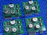
I am having a hard time finding the "exact" smd radial caps as shown in the attached pic. Any help on finding them and the pad size required would be appreciated. I have been searching digikey for electrolytics and polymers.
Thanks

I got confused by column F. My brain thought the resistors were all the same. lol about old age brain farts. All good
I am having a hard time finding the "exact" smd radial caps as shown in the attached pic. Any help on finding them and the pad size required would be appreciated. I have been searching digikey for electrolytics and polymers.
Thanks

The specs for the caps is in the BOM. It’s an SMT part - so specs different than normal pitch for pins and can diameter and height.
Maybe @JPS64 csn help? I think the photo shows ones built by @Vunce maybe he can chime in as to the part number. I myself build using stuff I have in my stock so not always the best at knowing the parts.
I think the third column shows the Series letter “F” or “G” etc and those correspond to this table as shown on a Panasonic SMD electrolytic cap datasheet.

The 5th column in the BOM shows the exact part number. For example:
C102/104 in the BOM below shows this part:
Which is a Panasonic 68uF “F” package according to this BOM for the MiniMELF IMS SMD board.

Maybe @JPS64 csn help? I think the photo shows ones built by @Vunce maybe he can chime in as to the part number. I myself build using stuff I have in my stock so not always the best at knowing the parts.
I think the third column shows the Series letter “F” or “G” etc and those correspond to this table as shown on a Panasonic SMD electrolytic cap datasheet.
The 5th column in the BOM shows the exact part number. For example:
C102/104 in the BOM below shows this part:
| 667-EEE-FK1J470P |
Which is a Panasonic 68uF “F” package according to this BOM for the MiniMELF IMS SMD board.
Last edited:
Thanks X,
I saw this also as I was checking / searching for the proper caps according to the BOM for the 0805/1206 smd's.
So if I understand correctly, according to the 0805/1206 BOM: for the 100Uf smd cap, I am looking for a CPOL_EUG Panasonic G, and according to the size code chart I would be looking for caps with the dimensions shown in the row for Size Code G.
Please correct me if I am wrong. I would like to order the parts, but wish I had the pcb's with me for verification on pad size, etc...
Thanks,
MM
BOM value 68uF is incorrect, schematic calls for 47uF
47uF - C102, C104
https://mou.sr/3vNDtPQ
100uF - C112
https://mou.sr/3VPHa2h
These are the parts listed in the BOM
47uF - C102, C104
https://mou.sr/3vNDtPQ
100uF - C112
https://mou.sr/3VPHa2h
These are the parts listed in the BOM
Thanks Vunce,
This clears up everything. I searched DK and found the same caps as you linked, checked the parameters against the chart that X posted, and Voila everything lines up perfect. Now I can finalize my order and await the shipment from the XRK Audio Shop.
Thanks everyone, for the help with this,
MM
This clears up everything. I searched DK and found the same caps as you linked, checked the parameters against the chart that X posted, and Voila everything lines up perfect. Now I can finalize my order and await the shipment from the XRK Audio Shop.
Thanks everyone, for the help with this,
MM
- Home
- Group Buys
- AKSA's Lender Preamp with 40Vpp Ouput GB